ASSEMBLY WORKSHOP
Bolt PWC mounts.
See the connections clearly. Follow each step, rotate the assembly and slide the parts apart.
Drag to rotate · Scroll to zoom
Mounts come from the current print geometry. Tube segments are shortened for clarity; use the aircraft cut list for full lengths. Fasteners and green bond bands are illustrations, not printable parts. Separation illustrates the connections, not an installation motion.
Read every assembly step
Landing gear mounts
- Identify the parts. Each side has one front block at X340 and one rear block at X410. Keep the PWC-specific lower axle nodes and gear-leg cut lengths; they differ from Bolt PC.
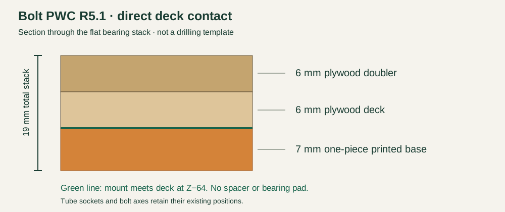
- Dry-fit the tubes. Use the full-size deck template and verify its 50 mm scale bar. The M4 holes are at X340/410,Y±25; the Ø3.3 mm holes are X356/394,Y±25. Seat the revised 7 mm printed bases directly against the plywood deck, with no separate pads. Fit the doubler and hardwood rails. Dry-fit the 12/10 mm carbon legs with 40 mm marked at each root.
- Install the fasteners. Use four M4×30 deck bolts with 18 mm OD steel washers on both faces, plus four M3×25 anti-rotation bolts with 7 mm OD washers; fit locknuts. Each fork separately uses M4×16 and M3×14. Check the measured stack and full locknut engagement; never tighten across a gap.
- Mark the bond areas. Green marks identify the 40 mm carbon root engagements and the wood-to-wood deck bonds. Wood patches indicate the mating surfaces, not isolated glue dots: bond the fitted doubler and hardwood rails across their contact areas. Qualify adhesive on actual materials. The printed gear blocks are mechanically retained; keep fastener seats, access pockets and moving joints free of adhesive.
- Check the assembly. Check that all four blocks bear flat without bending the deck, both fasteners are fitted to each block, the carbon legs are aligned in the gear jig, and the strut fork nuts remain accessible. Retain the matched PWC lower axle nodes, shell openings and rear collar.
R5.1: each printed base is 7 mm thick and meets the deck directly at Z−64. The printed base + deck + doubler stack is 7+6+6 = 19 mm. No separate bearing pads are needed. Dry-fit all four bearing faces before tightening and verify washers and full locknut engagement.
Fit and load testing are still required. The digital geometry screen does not qualify printed strength, adhesive bonds or flight performance. Use the specified structural material for the mounts, not foaming skin filament.