
3D Hangar · Current R2 package · 31 October 2026
Breeze 400 build guide
Interactive 3D viewerFree · name and email required
Print and fit prototype: physical printing, installed hardware and flight validation remain outstanding.
What changed
- Added complete snug and loose B01 body files matching the existing fit samples.
- Added one-body build plates for both alternatives; installed count remains 15.
These are digital design and documentation checks. No new physical print, load, radio, water or flight tests have been performed.
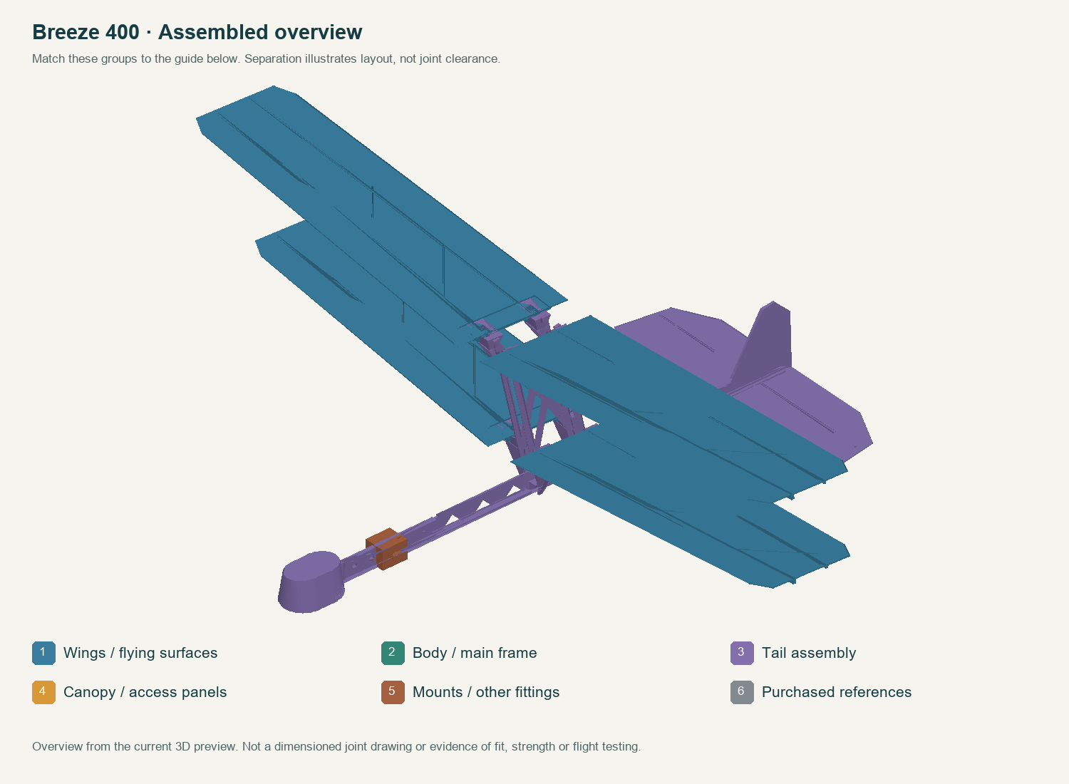
Before printing
Use the supplied orientation and 100% scale. The 3MF files contain geometry and arrangement, not a validated printer/material profile or ready-to-run G-code. Use the material listed for each plate. Slice with supports off where specified and inspect the first layers, bridges, thin-wall continuity and holes before printing.
Mounting and connection details
Coordinates refer to the assembled CAD datum, not the slicer’s rearranged plate. Dimensions below are millimetres unless stated otherwise.
| Interface | Dimension / part | Assembly action |
|---|---|---|
| Wing seat | Select nominal per-face clearance 0.06, 0.12 or 0.20 mm using the supplied matching coupon. | Print exactly one complete body with that clearance; a coupon alone does not change the production socket. |
| Wing locks | Eight K01 locks, two for each of four wing panels. | Seat each wing fully, fit its locks and pull gently by the root to verify retention. |
| Trim carriage | B02 carriage and one K02 lock. | Move only in small increments; verify the lock cannot slide under a gentle hand load. |
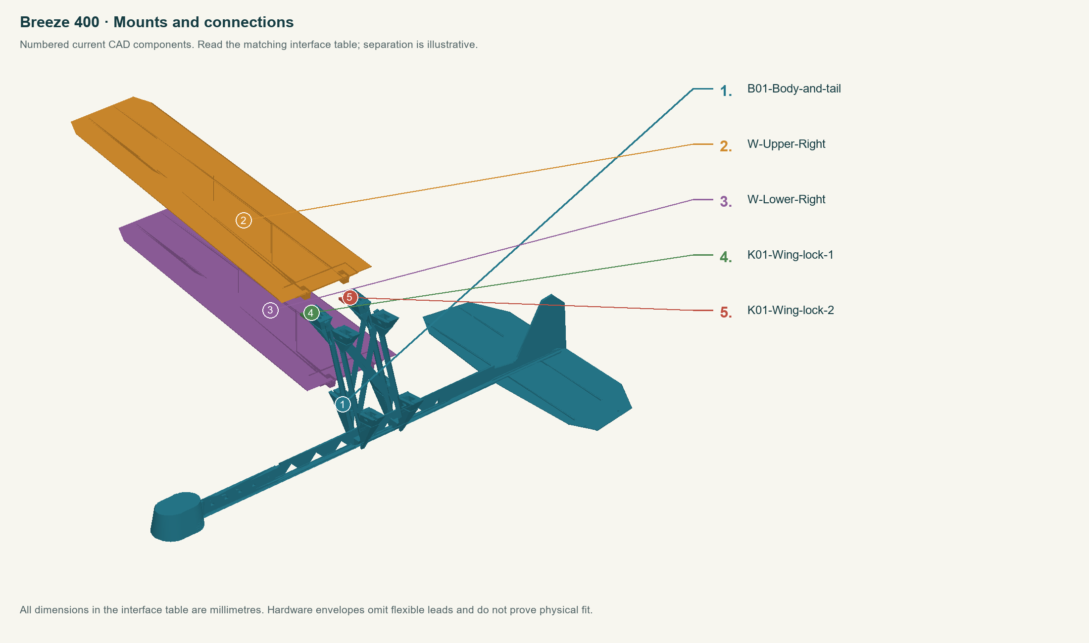
B01-Body-and-tailW-Upper-RightW-Lower-RightK01-Wing-lock-1K01-Wing-lock-2
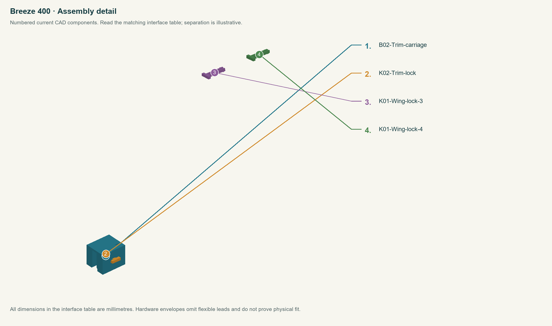
B02-Trim-carriageK02-Trim-lockK01-Wing-lock-3K01-Wing-lock-4
Build in this order
- Step 1
Print the complete functional test plate. Test default TEST-Seat with TEST-Wing-root and K01, the thin skin, and B02/K02 on TEST-Trim-rail. Snug/loose diagnostic samples are not matching full body variants; if only one of those fits, stop for a matching geometry revision. After coupon selection, use the matching complete body from Breeze-body-selection; print exactly one body.
- Step 2
Print B01 integral body/tail, four correctly named upper/lower left/right wings, eight K01 wing locks, B02 trim carriage and K02 trim lock in ordinary PLA with supplied orientations.
- Step 3
Fit the two lower wings first, then the two upper wings. Each wing takes two K01 locks, front and rear, with both barb shoulders emerging. Assembled wings have smooth faces up and ribs down. Reject cracked locks or rocking roots.
- Step 4
Fit B02 trim carriage to the forward rail, initially centered at 60 mm from the nose, and secure at a chosen hole with K02. Check it cannot slip during handling.
- Step 5
Measure the actual mass and balance against the provisional 132.9–135.3 mm-from-nose reference and verify the tall cabane and locks are stiff. The carriage has only about 1.13 mm predicted CG adjustment; if the measured balance is outside range the guide calls for design revision, not arbitrary added ballast.
- Step 6
Only progress to gentle unpowered glide evaluation after fit and balance checks; no physical print, load or successful glide is documented.
- Use the original 0.12 mm body if its coupon fits. Choose the 0.06 or 0.20 mm replacement only after testing the same filament and settings.
- No glue, carbon rods or metal fasteners are specified. Never force a lock into the thin wing or cabane.
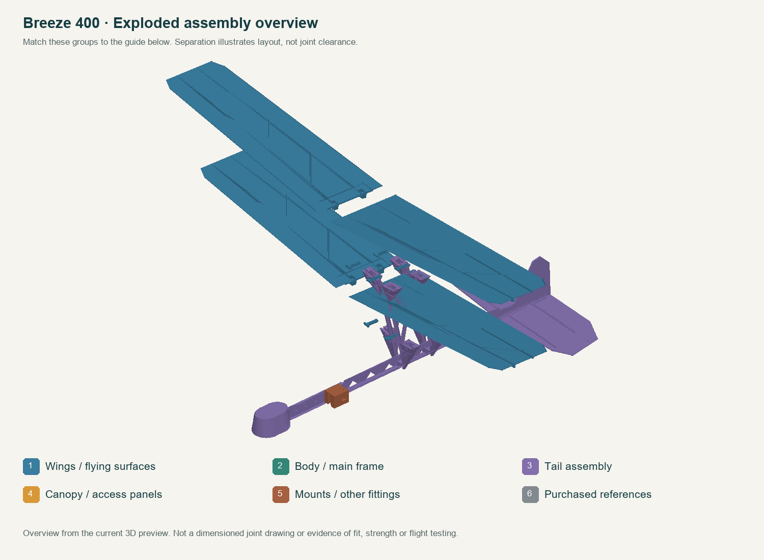
Fit and bond method
The intended assembly uses printed keys, sockets and retainers. Test the mating coupons first; do not conceal a loose or binding fit with an undocumented extra component. Keep working faces free of print burrs and replace cracked locks.
What still prevents a completed flying release
- Actual thin-wall printing, cabane and lock retention, measured mass/CG and glide tests.
Use the measurement record to report actual fits and test results. A geometric pass is not a structural rating, slicer validation or flight test.
Detailed source guide
Included in ZIP: Retained model-specific source instructions. Current R2 interface and replacement instructions above take precedence where a retained source describes an earlier revision.