
3D Hangar · R3 · 1 November 2026
Mount-only 3D views & step-by-step assembly →
Current R5 mount revision
Simpler mounts and numbered assembly diagrams · Complete current build plates · Required hardware changes
Use R5 mount instructions instead of earlier split-mount diagrams. Other airframe assembly instructions remain applicable. Print and dry-fit the mounts first.
Interactive 3D viewerFree · name and email required
Bolt PC build guide
Bench-build revision: geometry and assembly details updated; physical fit, structural and flight testing remain outstanding.
What changed
- Reoriented the strut joints to fore/aft pins and specified rod ends, spacers, studs and tube cuts.
- Split the two strut ribs into flat webs and upright spar cuffs; added matching wing/body clearances.
- Replaced the unspecified 8 mm axle with a dimensioned 6 mm shaft, collar and 5-inch wheel assembly.
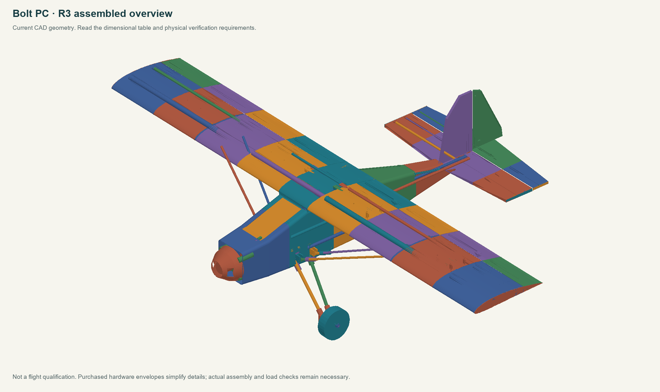
Before printing
Use 100% scale and the supplied orientation. These 3MFs are geometry-only, not printer profiles or G-code. Check the sliced first layers, bridges, thin walls and holes. Hardware cases and a digital clearance pass do not establish strength, fatigue, heat, radio reliability or flight performance.
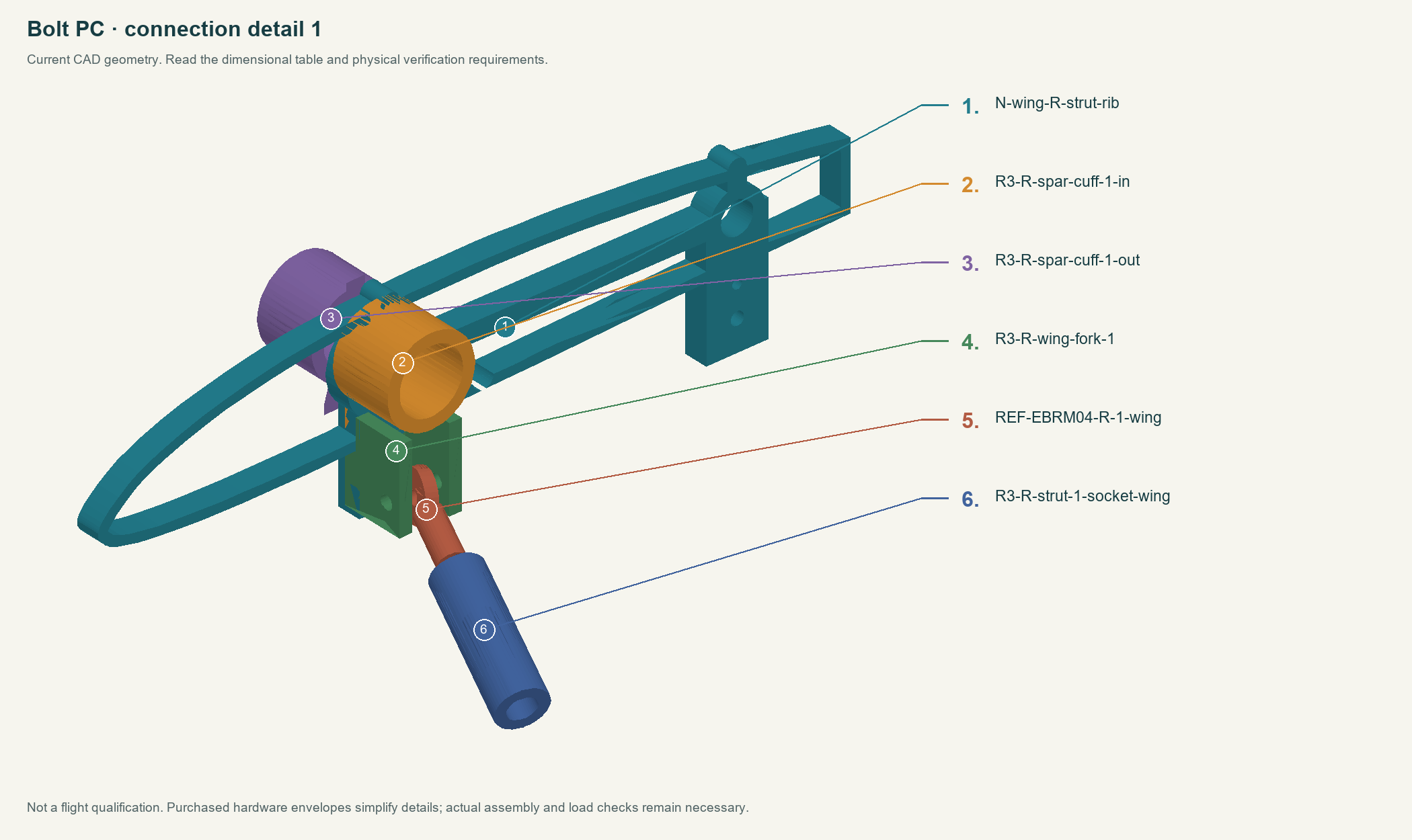
Strut joint and wing connection
| Interface | Current dimension / method |
|---|---|
| Pivot axis | Fore/aft X.12 mm clear fork; 4 mm cheeks. Ball 5 mm + two 3.5 mm spacers =12 mm. |
| Wing attachment | Existing M4 hole atZ143; new M3 hole atZ151. Wing fork pin atY±560, Z137. |
| Root attachment | Fork mounts atY±84. M4 atZ−37, M3 atZ−26. Root pivot atY±105, Z−37. |
| Rod-end engagement | 8 mm chosen; never below 7 mm and never bottom in 9.5 mm nominal threaded depth. |
| Tube-end offset | 40.7 mm per end =22.5 mm eye-to-mouth +3.2 mm jamnut +15 mm socket base.8 mm carbon enters socket 30 mm. |
| Side / run | Pivot distance (mm) | Nominal 8/6 tube cut (mm) | Ball misalignment |
|---|---|---|---|
| R 1 | 508.25 | 426.85 | 16.57° |
| R 2 | 521.77 | 440.37 | 20.99° |
| L 1 | 508.25 | 426.85 | 16.57° |
| L 2 | 521.77 | 440.37 | 20.99° |
The cut table uses the selected nominal end stack. Dry-fit both complete ends and measure the actual pivot distance before the final cut. Keep at least 7 mm engagement; do not lengthen a strut by loosening a rod end below that limit. The catalog 33° pivot allowance is a component limit, not a load rating for the printed fork.
Assemble the connections
- Print and test the actual carbon socket and fork fits in the intended conditioned material. Ordinary PLA is not a substitute for the specified structural-joint material. Complete a representative bonded-tube pull/twist test before bonding the aircraft.
- Dry-fit the wing and its continuous carbon members on the original alignment jig. Fit the flat 8 mm strut ribs and separate 21 mm cuffs on each side, preserving 50 mm total spar contact. Bolt the forks to the ribs before bonding cuffs.
- Install the root forks with the two-bolt pattern. Nuts sit in the open pockets, outside the carbon rails. Retain the original continuous tube engagement; do not drill the carbon to secure a fork.
- Install each EBRM04 eye with one 3.5 mm spacer on each side and the M4 pivot. Keep washers against the cheeks, not the eye housing. Tighten without crushing plastic or binding the ball; check actual articulation.
- Fit studs, jamnuts and captive socket nuts. Set 8 mm rod-end engagement, then measure and trim the four carbon struts using the table. Bond 30 mm into each socket on the wing jig. Struts must not pull an unaligned wing into position.
- Use the R3 replacement wing/body skins around the hardware. Check skin clearance with bolts, washers, horns and cables installed before closing seams.
Main gear and axle
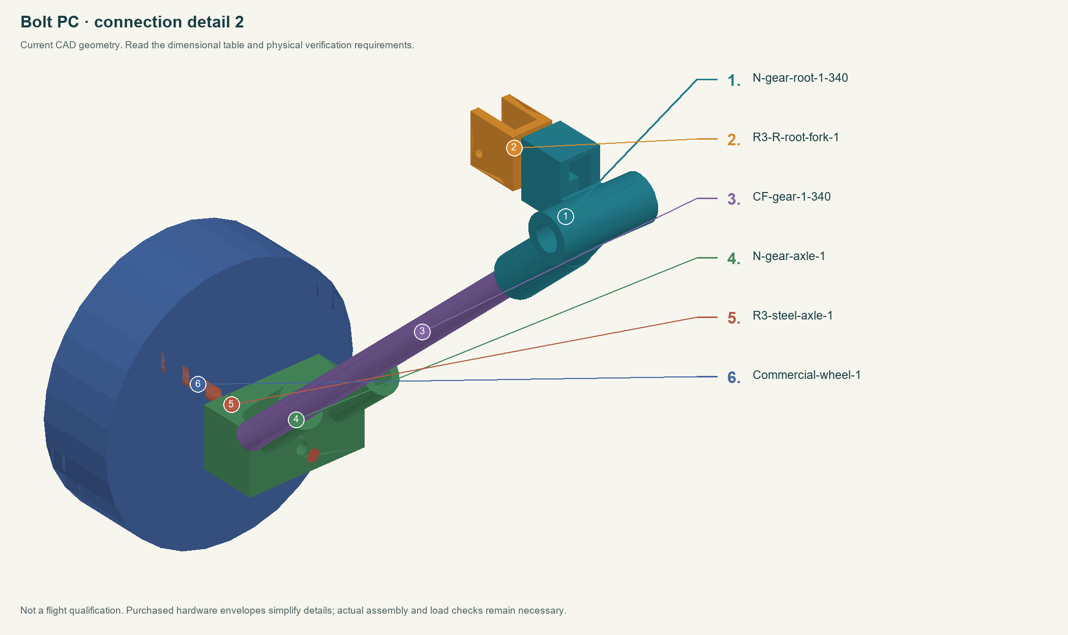
The gear is rigid triangulated carbon, not spring suspension. Use the correct lower node for this aircraft. Seat the carbon to the documented blind stops and verify wheel alignment on a jig before bonding.
| Shaft assembly, inboard → outboard | Axial width |
|---|---|
| MSP-6-F collar | 9 mm |
| Steel washer | 1 mm |
| Printed axle node | 28 mm |
| Steel washer | 1 mm |
| MSP-6-F collar | 9 mm |
| Steel washer | 1 mm |
| Wheel with total running clearance | 38.1 +0.4 mm |
| MSP-6-F outer collar | 9 mm |
| Total occupied stack / shaft | 96.5 /100 mm |
Set 0.2 mm clearance at each wheel face. Both sides of the printed node are retained by collars; the third collar retains the wheel. Verify that every collar is completely on the shaft, that screws are accessible, and that the wheel turns freely. No shaft-retention or landing-load rating is established by this geometric stack.
Retained airframe assembly
Follow the retained source guide for all unchanged structure and control surfaces. R3 connection, gear, cover and power instructions above replace older instructions for those interfaces.
In the download: Open the model-specific source assembly guide
Power and radio setup
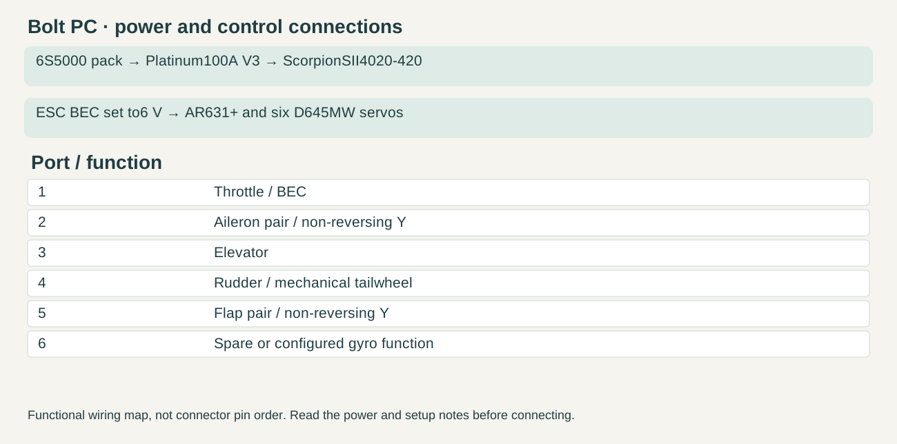
- Orient flap servos so a non-reversing Y produces matched flap movement.
- Verify all directions, throttle cut, failsafe and stabilization correction before fitting the purchased propeller.
Keep propellers removed (and Rotor motors disconnected) during setup. Check polarity and regulated bus voltage before plugging in the receiver/servos. Center servos before fitting horns; check neutral, direction and free travel before connecting rods. Configure throttle cut and receiver-loss response, then test them on the installed system.
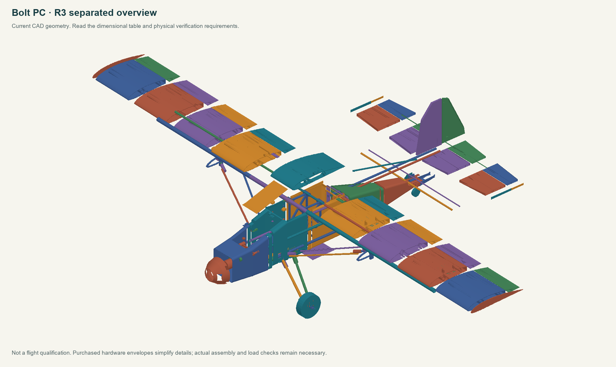
Verification still required
- Physical part/fastener fit, adhesive and structural proof tests, wheel retention and landing-load tests, radio/power checks, measured mass/CG and flight testing.
- R4 geometry checks cover the current print set. Physical toolpaths, bridging, bonds and load tests remain required.
No new physical print, load, electrical or flight tests have been performed. The current guides record what was checked digitally and what still needs measured evidence.