
Bolt PC · N-frame-X400
Interactive 3D viewerFree · name and email required
19 previous printed pieces → 3 current pieces. Numbered diagram shows only this replacement group.
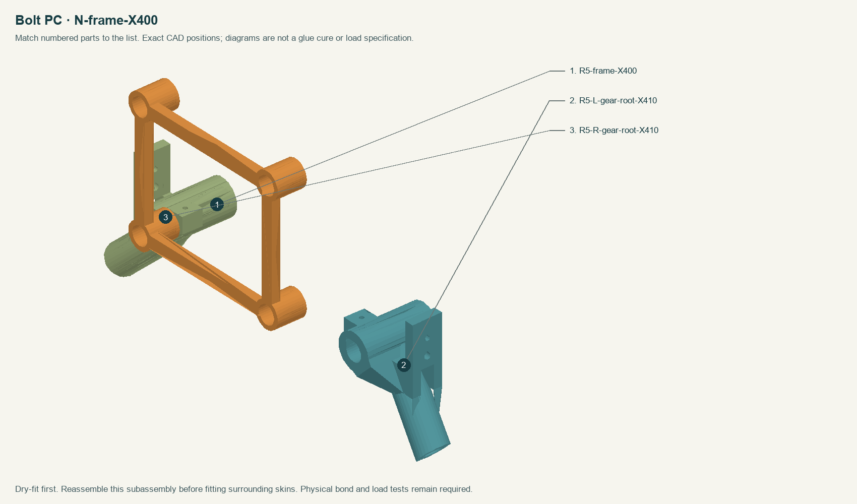
- In the download: R5-frame-X400 — Crossframe relocated to X366–386 between the gear sockets. Four 20 mm rail sleeves. Battery rear bolts remain X400,Y±42 on the rear gear nodes; do not put this frame at X400.
- In the download: R5-L-gear-root-X410 — One-piece gear node. Supplied 45-degree print orientation; 40 mm gear-tube insertion datum (do not bottom into the conical print relief). Accessible M4/M3 fork hardware. PWC uses M4x30 and M3x25 anti-rotation deck bolts; PC rear nodes support the battery tray at X400.
- In the download: R5-R-gear-root-X410 — One-piece gear node. Supplied 45-degree print orientation; 40 mm gear-tube insertion datum (do not bottom into the conical print relief). Accessible M4/M3 fork hardware. PWC uses M4x30 and M3x25 anti-rotation deck bolts; PC rear nodes support the battery tray at X400.