
3D Hangar · Current R2 package · 31 October 2026
Drift 420 build guide
Interactive 3D viewerFree · name and email required
Glide investigation: secure the tail and measure balance before another throw.
What changed
- Extended D01 keel rail from five to eight positions at 4 mm pitch: three new holes behind the old rear hole.
- Checked wing and saddle clearance at all eight positions. Retained wings and zero-degree tail geometry.
- Added a complete fit-selection print sequence and a separate bench balance stand.
These are digital design and documentation checks. No new physical print, load, radio, water or flight tests have been performed.
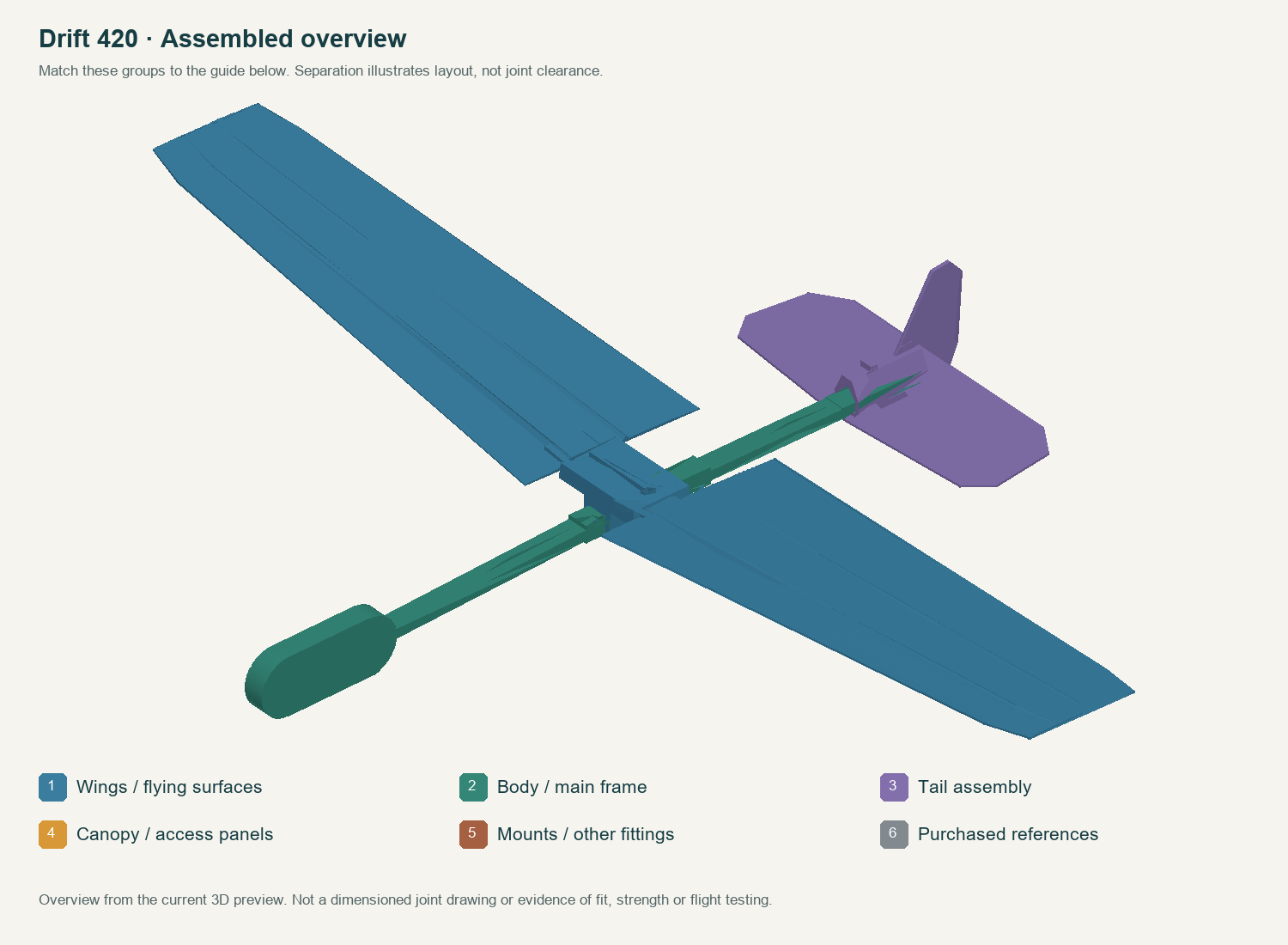
Before printing
Use the supplied orientation and 100% scale. The 3MF files contain geometry and arrangement, not a validated printer/material profile or ready-to-run G-code. Use the material listed for each plate. Slice with supports off where specified and inspect the first layers, bridges, thin-wall continuity and holes before printing.
Mounting and connection details
Coordinates refer to the assembled CAD datum, not the slicer’s rearranged plate. Dimensions below are millimetres unless stated otherwise.
| Interface | Dimension / part | Assembly action |
|---|---|---|
| Wing rail | Hole centers X141,145,149,153,157,161,165,169 mm; matching wing translations −8,−4,0,+4,+8,+12,+16,+20 mm. | Fit the saddle and position pin before the wing key. Never use a partly engaged pin. |
| Tail socket | Try S10, then S06, then S00 with the actual keel; select matching T10/T06/T00 zero-degree tail. | Choose the loosest fit that has no perceptible rocking. Do not force or enlarge the keel. |
| Tail pin | P260, P264 and P268 are alternatives, not three installed pins. | Try each with the selected tail and keel. The pin must seat fully and stay retained. |
| Balance | MAC reference = 59.077 mm; mean leading-edge X = 127.683 + selected wing translation. | Measure CG X with the complete plane. Percent MAC = 100 × (CG X − mean LE X) / 59.077. |
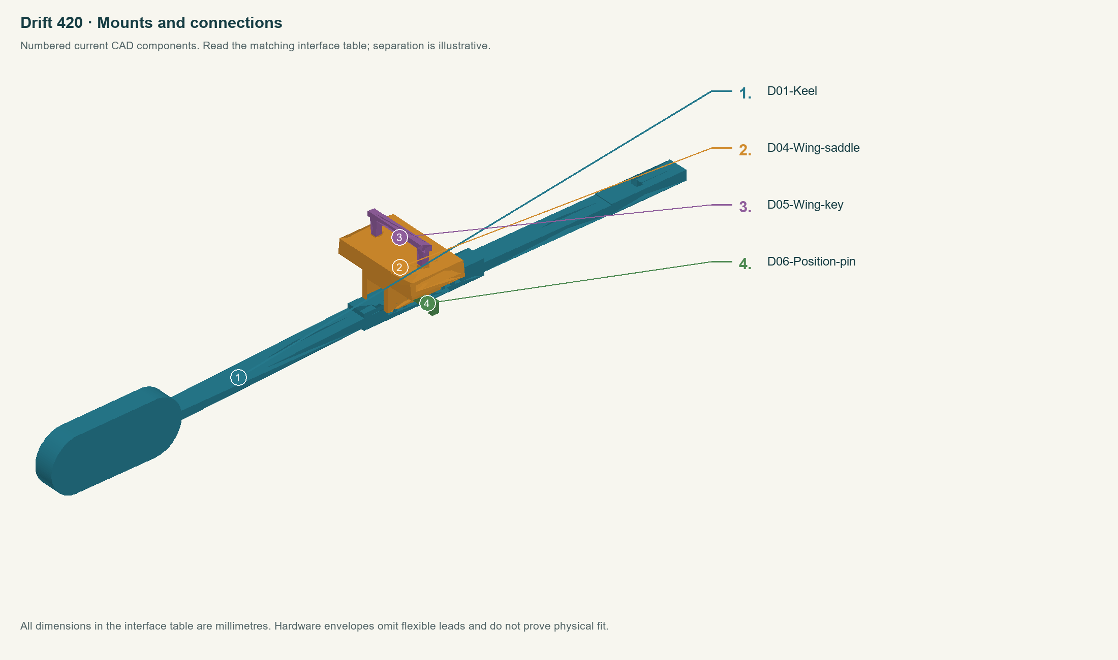
D01-KeelD04-Wing-saddleD05-Wing-keyD06-Position-pin
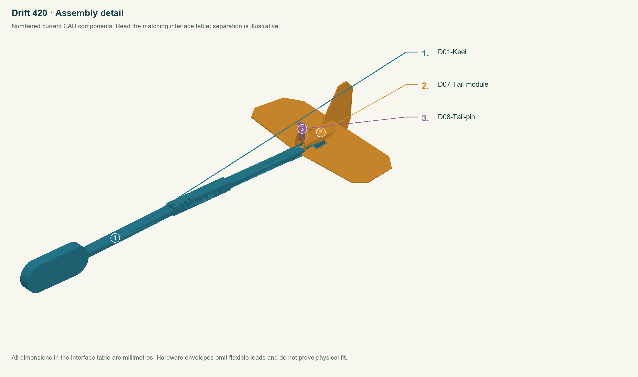
D01-KeelD07-Tail-moduleD08-Tail-pin
Build in this order
- Step 1
Print the complete mating set from Drift-fit-and-balance first. It includes the actual keys/pins and the alternative tail socket samples. Test with the same material and settings as the plane.
- Step 2
On the actual keel, try S10 then S06 then S00 socket trials and select one socket fit without tail rocking. Select one P260/P264/P268 pin by actual fit. These are unresolved trials, not a universally approved replacement set.
- Step 3
Use the new D01 eight-hole keel, one selected saddle, both wings, wing key and position pin. The three new aft holes add 12 mm adjustment. Record the chosen hole; the farther-aft positions are not automatically a flight trim recommendation.
- Step 4
Use exactly one selected complete zero-degree tail T10/T06/T00 matching the S trial, replacing D07, and one selected P pin replacing D08. Repeat fit checks with the complete tail; the pin must not be used to compensate for a rocking socket.
- Step 5
Record real assembled mass and numerical balance behind the wing leading edge with the wing position identified. Resolve the failed-glide cause and secure tail before further glide testing; the CAD balance marks alone do not demonstrate flight trim.
- The reported plane weighs 40 g and still has a loose tail. It previously flew a few feet and then dived. This revision does not establish the cause.
- The three added positions provide the requested adjustment range; do not assume the farthest-aft setting is correct. Record the selected hole and measured balance before further glide testing.
- Keep the baseline zero-degree tail while investigating fit and balance. Do not change tail incidence, wing position and throw strength simultaneously.
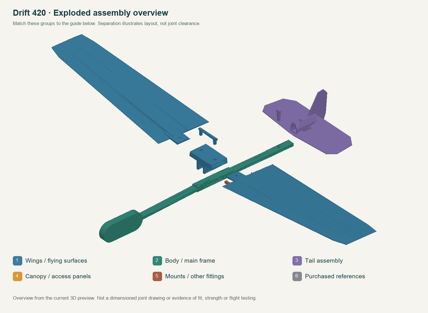
Fit and bond method
The intended assembly uses printed keys, sockets and retainers. Test the mating coupons first; do not conceal a loose or binding fit with an undocumented extra component. Keep working faces free of print burrs and replace cracked locks.
What still prevents a completed flying release
- Actual tail and pin selection; numerical CG measurement; repeatable gentle glide behavior.
Use the measurement record to report actual fits and test results. A geometric pass is not a structural rating, slicer validation or flight test.
Detailed source guide
Included in ZIP: Retained model-specific source instructions. Current R2 interface and replacement instructions above take precedence where a retained source describes an earlier revision.