Bolt PWC · simpler R5 mounts
R5.1 · gear mounts fit without pads
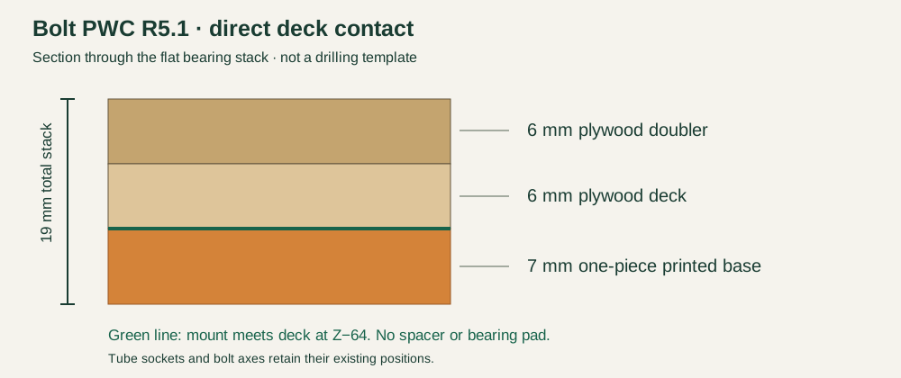
R5.1 closes the gear-deck gap in the four printed mounts. Each bearing base is now 7 mm thick and seats directly against the existing plywood deck. No separate bearing pads are needed. Use the same M4×30 and M3×25 deck bolts with washers and locknuts; the base + deck + doubler stack is 7+6+6 = 19 mm. Check actual washer thickness and full locknut engagement. Keep the supplied print orientations and inspect the sliced layers with supports off before printing.
Mount-only 3D views & step-by-step assembly →
Designed for supports-off printing in the supplied orientations. All current STLs pass a 0.20 mm geometric layer screen, with short two-ended bridges limited to 10 mm. Sliced toolpaths, actual printing, bond strength, landing loads and flight remain unverified.
Interactive 3D viewerFree · name and email required
The redesigned mount groups go from 12 to 4 printed pieces. Continuous webs and sleeves replace small glued sections. Some other airframe and tail groups still have multiple pieces.
This is an assembly simplification, not a weight-saving revision. The changed structural groups remove 49.2 cm³ of solid CAD volume; actual printed mass depends on material and slicing. Continuous material and bolted cage joints are intended to improve load paths, but strength still needs physical verification.
R5 gear deck hardware: four M4×30 bolts, eight 18 mm OD M4 steel washers and four M4 locknuts; add four M3×25 bolts, eight 7 mm OD M3 washers and four M3 locknuts. The original fork fasteners remain separate. Deck/doubler thickness is 6+6 mm; the new printed base is 6 mm.
Assembly order
- Print the four gear nodes in their supplied orientations. Each side now uses one front node at X340 and one rear node at X410. Keep the PWC-specific carbon leg lengths and lower nodes.
- Print the drilling template at 100% and verify its 50 mm scale bar. Align the four existing M4 hole centers at X340/410,Y±25. Add four Ø3.3 mm anti-rotation holes at X356/394,Y±25 through the 6 mm deck and 6 mm plywood doubler. The 110×80 mm doubler stays centered at X375,Y0.
- Use four M4×30 bolts with 18 mm OD load-spreading washers on both faces and locknuts. Add four M3×25 bolts, two 7 mm OD washers and one locknut each. Check the 7+6+6 mm printed/deck/doubler stack, real washer thickness and full locking engagement. Do not rely on one bolt per block.
- Use both matching R5 F02 body sections and the R5 X385 collar; clearance channels remain open behind the gear gussets. Retain the original hardwood deck rails and bond instructions.
In the download: Full-size PWC drilling template
Tube fit and glue
- Print the retained tube-fit and adhesive samples in the intended structural material. The load-bearing mounts use the PAHT-CF candidate profile; do not substitute foaming skin filament. Actual material and adhesive compatibility must be qualified.
- Clean up only the brim and minor bore fuzz. A dry-fit should slide without cracking the printed socket. Do not enlarge holes indiscriminately or force carbon tubes.
- Mark 40 mm insertion on each gear tube and align to its modeled root datum. The conical cavity behind the round socket exists for printing; it is not an insertion stop. Use the tube centerlines and original gear jig to set angles.
- Dry-assemble the complete rail/gear/cabin group, battery tray, servo tray and adjoining skins before bonding. Ensure the four gear nodes are square and the strut fork hardware remains accessible.
- Bond with the qualified adhesive and hold the continuous carbon members in a straight jig during cure. Keep bolt seats, access pockets and moving joints clear.
- Check rail bonds, bolted joints, landing loads and motor vibration using the existing aircraft test plan before considering powered flight. Fit success alone is not structural qualification.
Replacement map
| Mount or surrounding part | Old pieces | New pieces |
|---|---|---|
| R4-F-collar-X385 | 1 | 1 |
| F-02-body--R4-01 | 1 | 1 |
| F-02-body--R4-02 | 1 | 1 |
| R3-L-gear-and-strut-cradle | 6 | 2 |
| R3-R-gear-and-strut-cradle | 6 | 2 |
In the download: Geometry screen record