
3D Hangar · R3 · 1 November 2026
Transport 1829 build guide
Interactive 3D viewerFree · name and email required
Bench-build revision: geometry and assembly details updated; physical fit, structural and flight testing remain outstanding.
What changed
- Replaced tape-only retention on three service covers with 12 M2 screws, reinforced cover lands and captured nuts.
- Enlarged and relieved the regulator board for two UBEC25A HV units; kept both propulsion batteries.
- Specified separate eight-branch power collectors, isolated PowerSafe inputs and a loaded single-supply/failover test sequence.
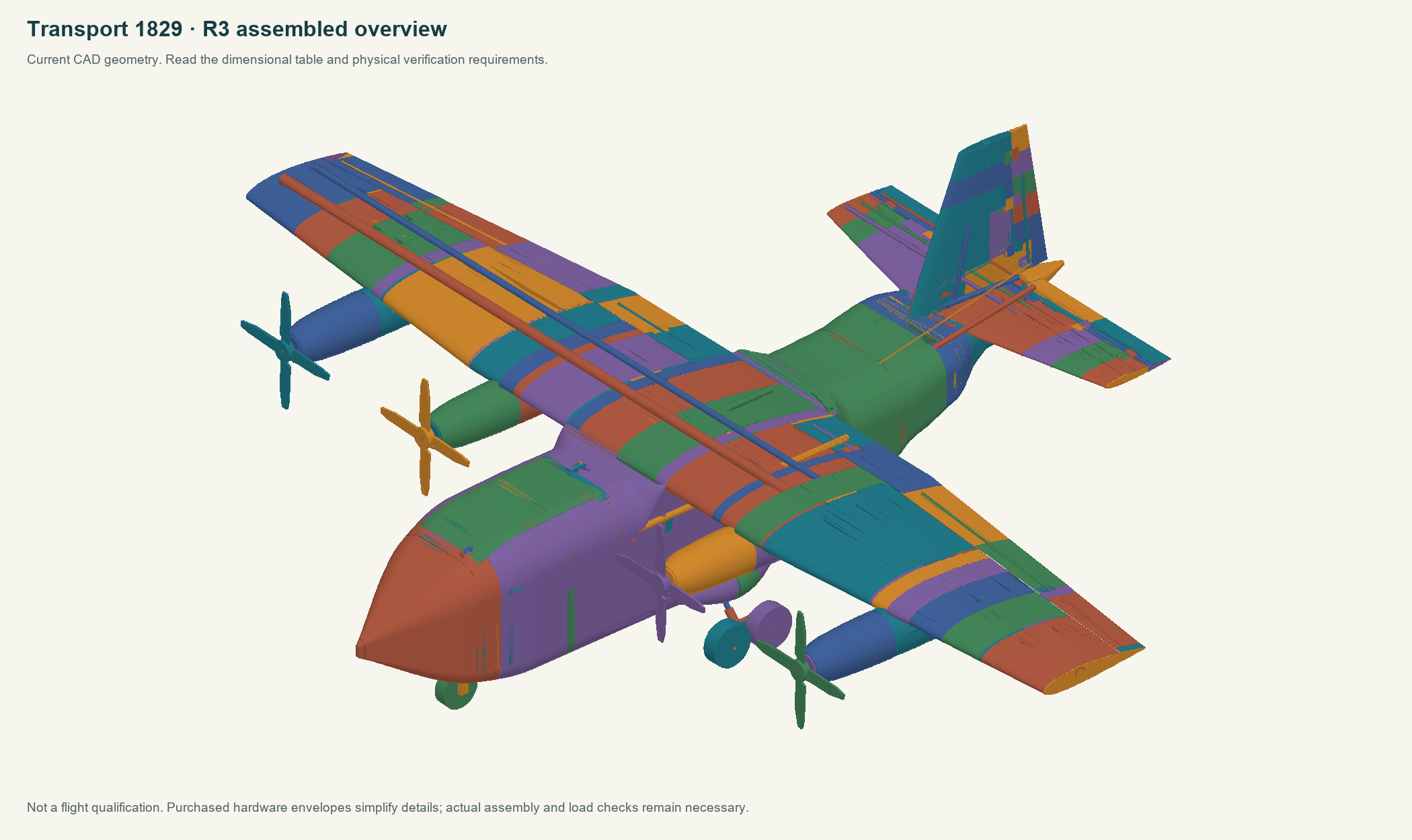
Before printing
Use 100% scale and the supplied orientation. These 3MFs are geometry-only, not printer profiles or G-code. Check the sliced first layers, bridges, thin walls and holes. Hardware cases and a digital clearance pass do not establish strength, fatigue, heat, radio reliability or flight performance.
Service covers and battery hatch
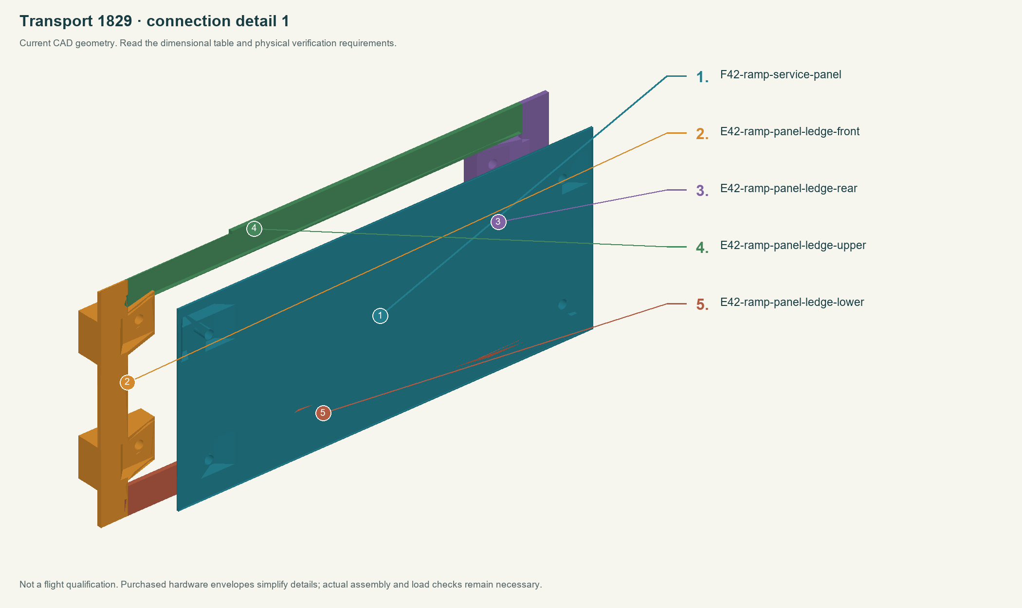
- Print the three R3 covers in ordinary PLA, and the six revised front/rear ledges in ASA. The covers have four reinforced mounting lands each. Retain the existing upper/lower locating ledges.
- Fit twelve M2 nuts into the open inside pockets. A tiny compatible adhesive dot may retain a nut only on its outside flats; keep threads clear.
- Dry-fit each cover on all four ledges. Use the assembled shell as the alignment jig, then bond only the fixed-shell lands of the ledges. Keep a nominal 0.30 mm perimeter gap and keep adhesive off the removable cover.
- Install four M2×10 screws with 5 mm OD washers per cover. Verify full nut engagement and moving-linkage clearance; tighten by hand without crushing the skin. Tape is no longer the specified primary retention.
- Retain the battery canopy’s eight 8×3 mm magnets, front tabs and mechanical turnbutton. Check polarity before caps are bonded. The turnbutton must capture the canopy independently of magnet pull.
- With both batteries disconnected, release straps, lift each pack 6 mm, slide 90 mm forward and lift out. Repeat with the real pads, plugs and restrained collector wiring. Close and latch the canopy without pinching leads.
Two-battery receiver power
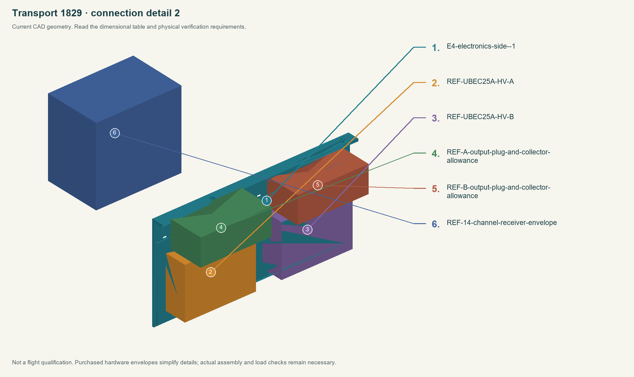
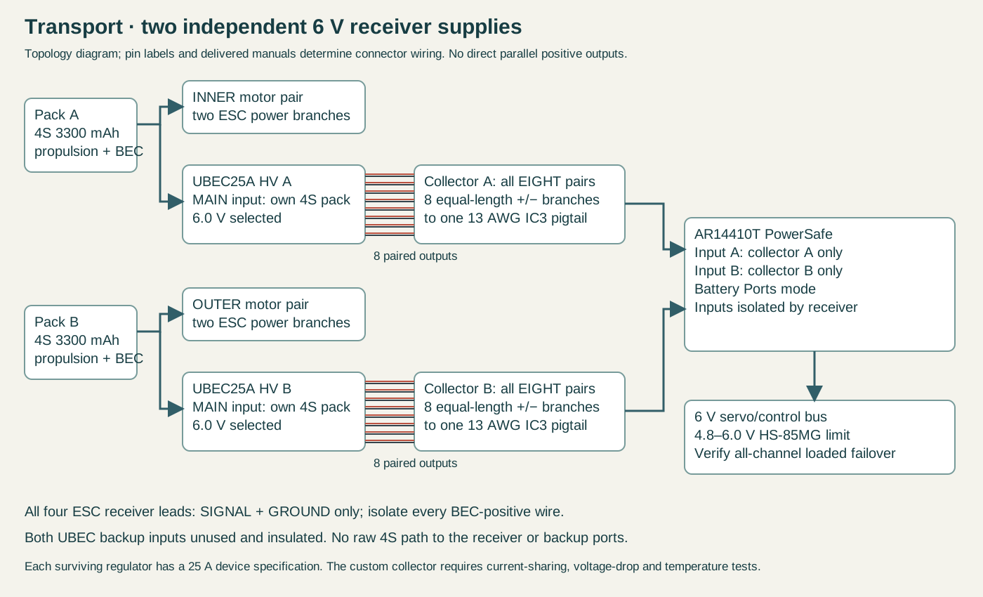
Each 4S3300 pack powers its own motor pair and its own UBEC25A HV. Set both regulators to 6.0 V. Connect each collector to a separate AR14410T battery input and retain Battery Ports mode. Remove and individually insulate all four ESC BEC-positive pins; retain signal and ground.
The receiver maker documents isolated inputs and takeover from the remaining source. This exact cross-brand system is an engineering selection from published interfaces, not a manufacturer-approved assembled system. The surviving regulator is specified 25 A, not 50 A redundant capacity. HS-85MG servos limit the bus to 6.0 V.
| Regulator location | Case-only allowance |
|---|---|
| A | X205–260, Y−77.6..−60, Z−15..25.2 mm |
| B | X280–335, same Y/Z |
| Output plugs / collector allowance | Above each case: Z27–48, Y−87.6..−60. Actual plug/bend fit must be checked. |
| Retention | Two 8 mm straps per case; 1.6 mm pad; open cooling faces. More than 50 mm geometric separation from receiver. |
Build each collector
- Use all eight manufacturer-supported output+/− pairs from one regulator. The supplied four double-ended 100 mm JR cables provide eight plug ends if the delivered kit matches the manual. Keep branch lengths equal.
- Join all eight positive wires of A to one A IC3 positive lead, and all eight grounds to its ground lead. Repeat separately for B. Remove/insulate all signal wires. Verify every pin by its label and continuity, never by an assumed wire color.
- Use insulated, mechanically supported multi-wire joins and strain relief; each conductor must be fully captured. Retain all eight plug housings against vibration. Do not put a single JR connector or ordinary Y lead after the collector.
- Keep A and B positive outputs separate. Leave both backup battery inputs unused and insulated; they are not 4S inputs. Do not connect raw 4S to the receiver.
- Do not assign the custom harness a 25 A rating from the regulator label. Measure current sharing, voltage drop and temperature through the installed collector and connectors before flight.
Commission power before fitting propellers
- Disconnect motors/propellers. Verify polarity, continuity, separation of positive inputs and absence of any raw 4S path to the receiver.
- With the receiver disconnected, measure each regulator separately at 6.0 V. For the documented UBEC, switches 1 OFF, 2 OFF, 3 ON select 6.0 V; confirm the delivered manual.
- Power receiver from A alone, then B alone. Verify binding, Battery Ports mode, analog-compatible servo timing, directions, throttle cut and receiver-loss motor stop for both throttle groups.
- Exercise all controls and the complete latch/door/ramp/release sequence under representative controlled resistance. Do not deliberately stall servos. Log rail voltage, total and branch current, temperatures and receiver resets. HS-85MG operating range is 4.8–6.0 V.
- Repeat on each source alone. With motors disabled and both supplies working, turn one regulator off and confirm uninterrupted controls, restore it, then repeat the other. Do not simulate failure by shorting a battery.
- Check final antenna routing/range, pack-voltage reserve, wire bends and hatch retention. PowerSafe receiver-side consumption telemetry is not total propulsion-pack consumption.
Retained airframe assembly
Follow the retained source guide for all unchanged structure and control surfaces. R3 connection, gear, cover and power instructions above replace older instructions for those interfaces.
In download: Open the model-specific source assembly guide
Control channel map
| Channel | Function |
|---|---|
| 1 | Inner throttle pair / Y |
| 2 | Left aileron |
| 3 | Elevator |
| 4 | Rudder |
| 5 | Left flap |
| 6 | Right aileron |
| 7 | Right flap |
| 8 | Outer throttle pair / Y |
| 9 | Nose steering |
| 10 | Ramp |
| 11 | Upper door |
| 12 | Latch |
| 13 | Release gate |
| 14 | Spare |
Confirm NX8 firmware supports the expanded channels before binding this plan. Actual AirWare version has not been inspected. Test the complete latch → door → release sequence with inert payloads on the ground.
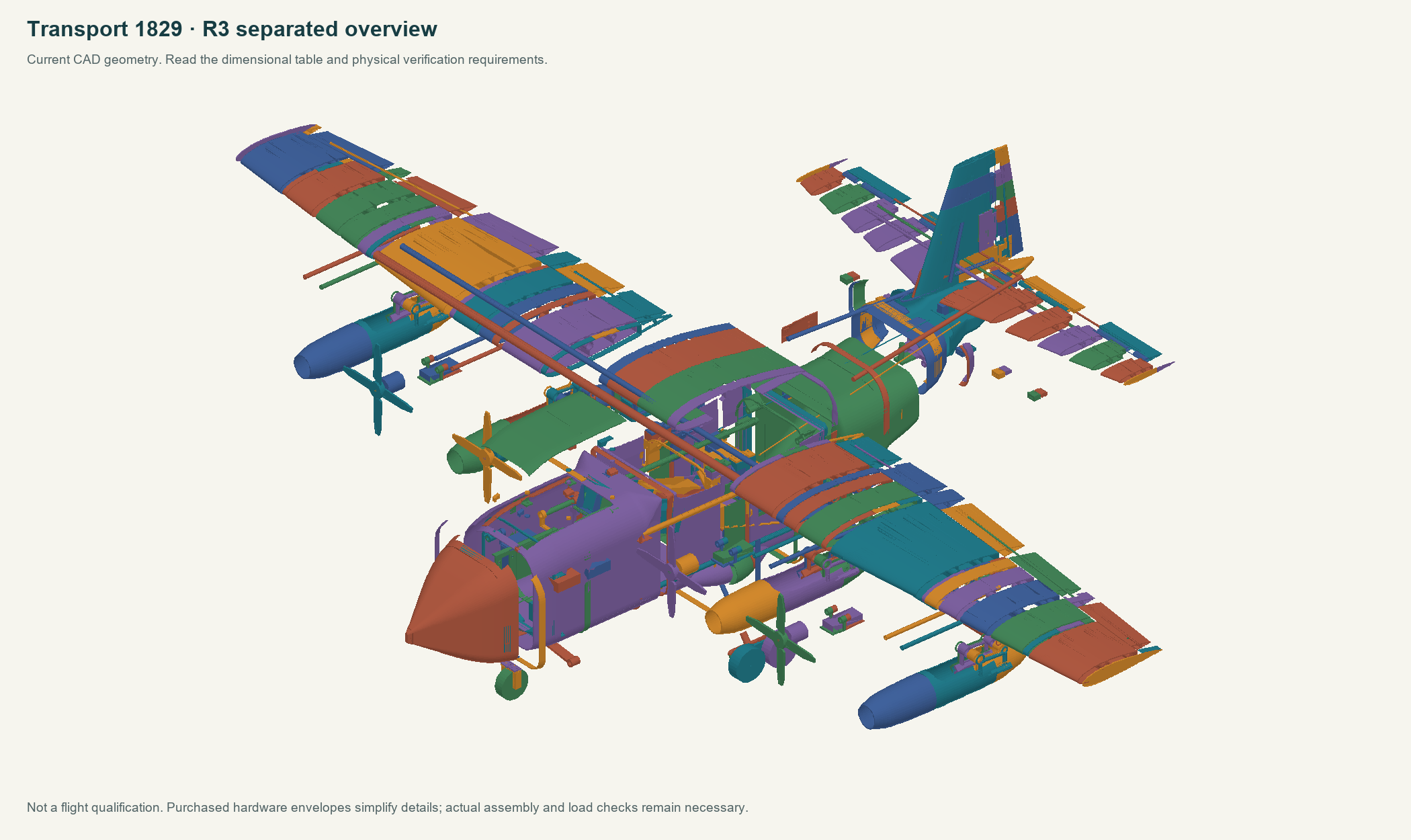
Verification still required
- Actual connector/receiver-grommet fit and lead routing; custom collector current-sharing/temperature, loaded single-supply/failover tests, cover pull/vibration checks, propulsion/CG/payload and flight qualification.
No new physical print, load, electrical or flight tests have been performed. The current guides record what was checked digitally and what still needs measured evidence.