
3D Hangar · Current R2 package · 31 October 2026
Wisp 560 build guide
Interactive 3D viewerFree · name and email required
Print and fit prototype: physical printing, installed hardware and flight validation remain outstanding.
What changed
- Added a numbered shaft, bearing and propeller assembly drawing, plus a separate wing-lock drawing.
- Retained both frame-slot coupons on the functional PLA plate; clarified printed lock assembly and winding-test limits.
These are digital design and documentation checks. No new physical print, load, radio, water or flight tests have been performed.
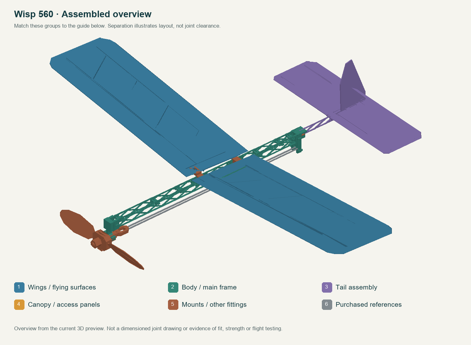
Before printing
Use the supplied orientation and 100% scale. The 3MF files contain geometry and arrangement, not a validated printer/material profile or ready-to-run G-code. Use the material listed for each plate. Slice with supports off where specified and inspect the first layers, bridges, thin-wall continuity and holes before printing.
Mounting and connection details
Coordinates refer to the assembled CAD datum, not the slicer’s rearranged plate. Dimensions below are millimetres unless stated otherwise.
| Interface | Dimension / part | Assembly action |
|---|---|---|
| Printed drive | P04 shaft-eye, F03 bearing, F08 lower cap and two K04 cap locks. | Seat the bearing and cap first. Fit the shaft in the illustrated axis; it must turn freely without perceptible cracking or binding. |
| Propeller | Two P01 blades, P02/P03 hub halves, P06 retainer and two P07 printed locknuts. | Match blade handedness and hub keys. Seat both nuts without splitting the printed threads; check axial retention and blade symmetry. |
| Rubber anchor | F04 rear anchor, F05 axle and F07 keeper. | The rubber loop is the only nonprinted flight part. Fit it between the printed shaft eye and rear anchor; protect it from sharp edges. |
| Wing lock | W03/W04 saddle halves, W05 index keys and four W06 root keys. | Dry-fit the mating samples first. Keep left/right panel alignment and fully engage each key. |
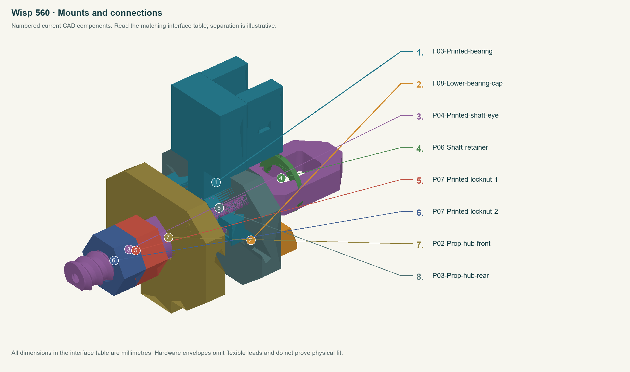
F03-Printed-bearingF08-Lower-bearing-capP04-Printed-shaft-eyeP06-Shaft-retainerP07-Printed-locknut-1P07-Printed-locknut-2P02-Prop-hub-frontP03-Prop-hub-rear
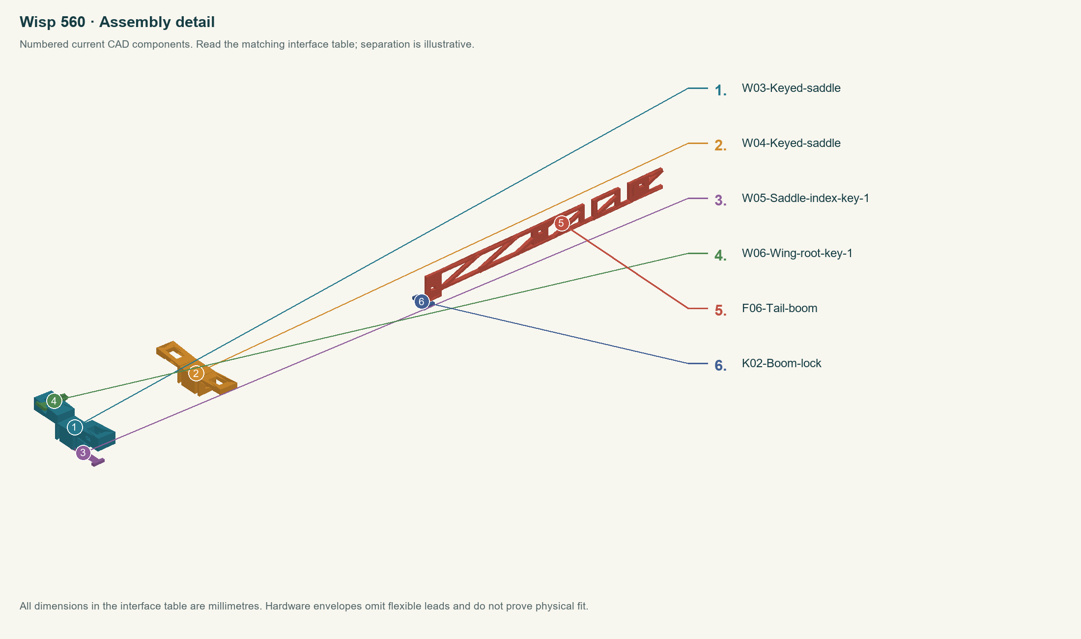
W03-Keyed-saddleW04-Keyed-saddleW05-Saddle-index-key-1W06-Wing-root-key-1F06-Tail-boomK02-Boom-lock
Build in this order
- Step 1
Use the complete functional test plates and Print-first procedure: printed shaft/thread, closed dry bearing/cap, two blade-root coupons in the hub, frame snap, wing-root latch, rear rubber anchor and thin Aero skin. The current PLA functional plate needs a second TEST-Frame-slot copy to match the procedure.
- Step 2
Build the two F01 side rails with six F02 snap braces. Install F03 printed upper bearing and F04 rear anchor, secure with K01 keys, then fit F06 tail boom with K02. Confirm latch shoulders emerge without cracks or rocking.
- Step 3
Fit W03/W04 saddles to matching rail indices with two W05 keys. Fit W01/W02 wings with four W06 root keys, smooth faces up and ribs down. Fit T01 horizontal tail and T02 fin with four K03 locks.
- Step 4
Lay P04 shaft radially into F03, close F08 lower bearing cap and secure with two K04 keys. Fit P06 retainer into the rear shaft groove; verify free rotation dry without rubbing.
- Step 5
Capture two P01 blade T-roots between P02/P03 hub halves, engage keyed shaft drive, finger-tighten one P07 nut and then a second jam nut. Full closure, fixed blade pitch and static balance remain required; custom 6 mm/2.4 mm-pitch printed nuts are not standard M6 metal hardware.
- Step 6
Route the one rubber loop from the shaft eye to F05 rear axle through F04; fit F07 keeper. Check alignment and retention. About twenty gentle hand turns in the source guide are only a direction/friction ground check, not a safe working winding limit.
- Step 7
Measure mass/CG, qualify the complete dry mechanism and retention, and establish repeatable unpowered glide behavior before powered tests. A safe winding/load envelope and flight performance have not been established.
- Do not add oil, a hidden metal shaft or glue to make an unsuccessful rubber-only trial appear complete. Correct the printed fit first.
- No safe winding count has been measured. Begin with an unwound inspection and free shaft rotation; any winding test needs a guarded bench setup and inspection after each small increase. A printed propeller is experimental.
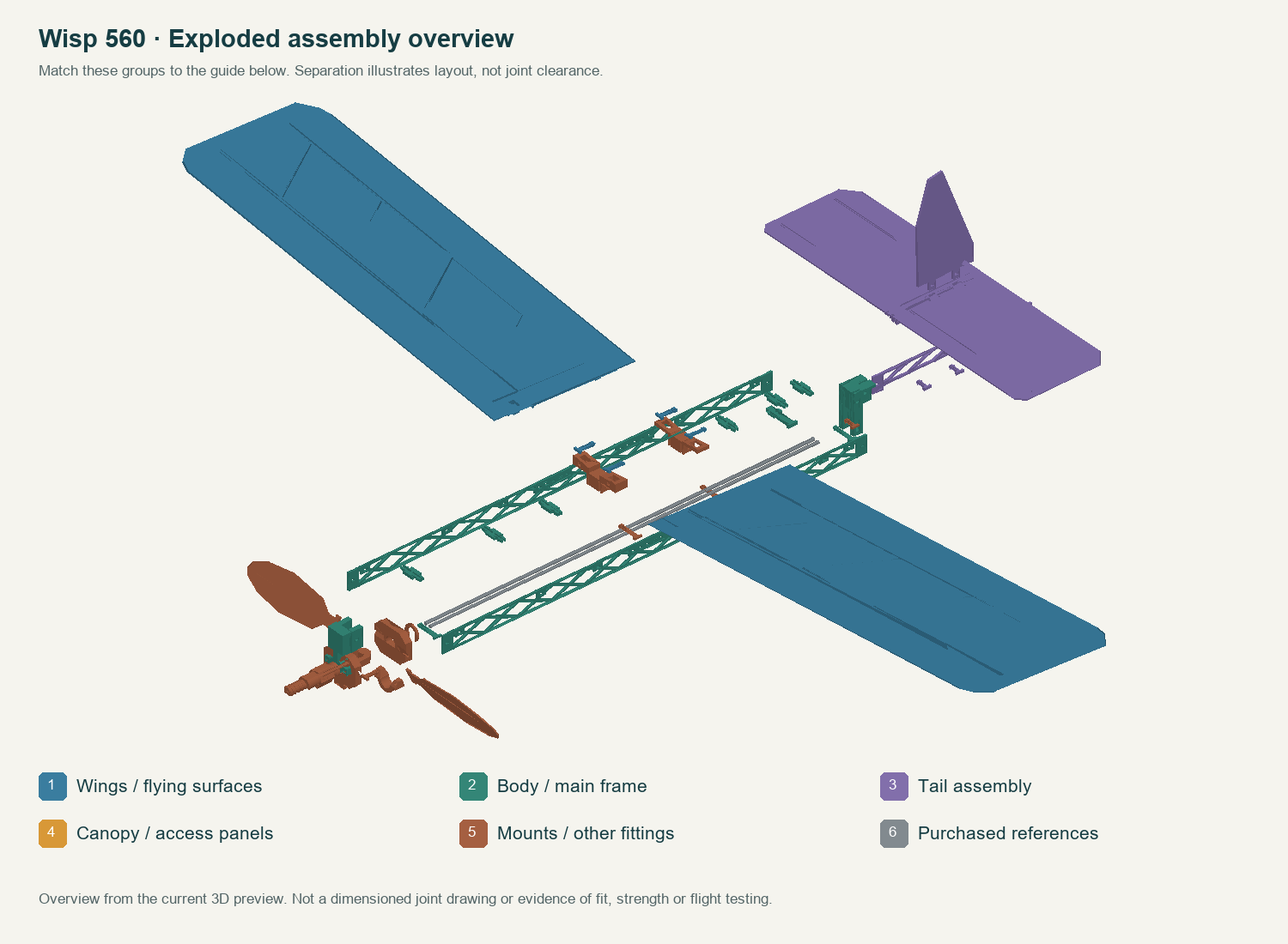
Fit and bond method
The intended assembly uses printed keys, sockets and retainers. Test the mating coupons first; do not conceal a loose or binding fit with an undocumented extra component. Keep working faces free of print burrs and replace cracked locks.
What still prevents a completed flying release
- Printed shaft friction, hub/lock strength, rubber-load retention and an established winding limit; measured glide and powered-flight performance.
Use the measurement record to report actual fits and test results. A geometric pass is not a structural rating, slicer validation or flight test.
Detailed source guide
Included in ZIP: Retained model-specific source instructions. Current R2 interface and replacement instructions above take precedence where a retained source describes an earlier revision.