
3D Hangar · Rotor 235 · 1 November 2026
Exactly what to buy and measure
Interactive 3D viewerFree · name and email required
The primary frame stays printed. This is a parts-based measuring kit, not a whole helicopter. Order one retail packet of every SKU below, except the three KST servos. Packet quantities and installed quantities differ.
Start with groups A–D for frame interfaces; group E completes the rotor head for the final unpowered linkage sweep. Electronics, batteries and controllers can wait for mechanical fit checks; their current selection remains in Parts and equipment.
Download the shopping checklist · Download the blank measurement record · Print the six-piece measuring fixture
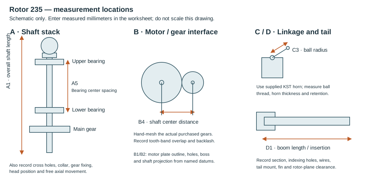
Use millimeters, digital calipers, a small square and a flat surface. Record actual readings, the measurement points and clear front/side photos. Do not scale dimensions from a product photograph. Motors remain disconnected throughout this measuring work.
A · Shaft and bearings
| Buy | Exact part | Contents / use |
|---|---|---|
| 1 packet | BLH1506 Main-shaft set | Buy 1 packet; two shafts supplied, one used plus one spare. BLH1506. 2 shafts, 1 locking collar and set screw Exact shaft geometry is unmeasured. Do not print this shaft. |
| 1 packet | BLH4515 Main-shaft bearings | Buy 1 packet of three; two bearing positions are shown, third is spare. BLH4515. 3 bearings, 4 x 8 x 3 mm 4 mm ID / 8 mm OD / 3 mm width. Drawing p 19 shows two callout-27 rings; pack quantity is three. Stock and final installed count must be checked against the mechanism. US source showed backorder; no substitute specified. |
| 1 packet | BLH1402 Main gear and fixing hardware | Buy 1 retail packet / unit. BLH1402. 1 main gear, shoulder bolt and locknut Module, tooth count, bore, thickness and shoulder-bolt geometry not published in reviewed sources. |
| 1 packet | BLH-1773 Aluminum rotor-head block | Buy 1 retail packet / unit. BLH-1773. 1 head block, shoulder bolt and locknut This is NOT a complete assembled rotor head. The following spindle, dampers, grips, bearings, links, blades and bolts are separate. |
Measurements to send back
| ID | Measurement / observation | Your result, mm or notes |
|---|---|---|
| A1 | Shaft overall length and diameter; measure diameter at top, middle and bottom. | ________________________ |
| A2 | From the shaft bottom end to each cross-hole center; record hole diameters and any flats/shoulders. | ________________________ |
| A3 | Gear thickness, hub height/diameter, fixing-hole center and assembled gear-to-lower-bearing distance. | ________________________ |
| A4 | Collar height and clamping range; bearing ID/OD/width and shoulder contact faces. | ________________________ |
| A5 | Assemble gear, bearings, collar and head block by hand. Record bearing center spacing, head cross-hole position and axial end float without binding. The fixture’s 60 mm spacing is adjustable, not a target. | ________________________ |
B · Main motor and gear mesh
| Buy | Exact part | Contents / use |
|---|---|---|
| 1 packet | SPMX-1083 Main brushless motor | Buy 1 retail packet / unit. SPMX-1083. 1 3400 Kv brushless outrunner Manual identifies 14 poles. Published mount pitch, shaft diameter and mass were not found. |
| 1 packet | BLH-1781 OEM motor mounting plate | Buy 1 retail packet / unit. BLH-1781 includes four M2×6, two M3×6 and washers. Its attachment pattern must be measured for the printed frame. |
| 1 packet | BLH-1785 Motor pinion | Buy 1 retail packet / unit. BLH-1785. 1 13-tooth pinion and set screw Tooth count is verified; bore/module/mesh-center spacing are not. |
Measurements to send back
| ID | Measurement / observation | Your result, mm or notes |
|---|---|---|
| B1 | Plate outline/thickness; frame attachment-hole centers and diameters from a named edge. Photograph both sides. | ________________________ |
| B2 | Motor case, locating boss, shaft diameter/length and motor mounting-hole coordinates. | ________________________ |
| B3 | Motor mounting thread and usable screw engagement, excluding winding clearance. Do not probe or force a screw into windings. | ________________________ |
| B4 | Installed pinion tooth-band height, main-gear tooth-band height and shaft-to-shaft center distance with smooth hand rotation through 360°. Photograph mesh; record backlash/runout, not just tooth count. | ________________________ |
C · Swash and servo linkage
| Buy | Exact part | Contents / use |
|---|---|---|
| 1 packet | BLH-1775 Aluminum swashplate | Buy 1 retail packet / unit. BLH-1775. Swashplate including linkage balls and anti-rotation guide pin |
| 1 packet | BLH-1783 Swashplate anti-rotation bracket | Buy 1 retail packet / unit. BLH-1783. Bracket with 2 M2x6 screws Recommended purchased guide for first printed-frame mechanism. A printed replacement still needs exact pin clearance and travel measurements. |
| 1 packet | BLH-1780 Cyclic servo links | Buy 1 retail packet / unit. BLH-1780. 3 threaded rods and 6 ball links |
| 1 packet | BLH-1793 Servo horn / link-ball set | Buy 1 retail packet / unit. One packet supplies three horns, three link balls, three M2×6 screws and three lock washers. Use the balls and hardware as the matched linkage reference; measure retention on the KST arms before choosing final fasteners. OEM horns are reference pieces, not a claimed KST spline match. |
| 3 servos | KST DS215MG V8 KST cyclic servo with its supplied horns | Buy 3 individual servos; retain their supplied KST arms and center screws. Three servos, each supplied with five plastic horns and its own retaining screw. Keep the KST horns; do not assume the Blade horn spline fits. |
Measurements to send back
| ID | Measurement / observation | Your result, mm or notes |
|---|---|---|
| C1 | Antirotation bracket hole centers, thickness and slot position relative to main-shaft center. | ________________________ |
| C2 | Swash guide-pin diameter; usable slot length and axial swash range before contact. | ________________________ |
| C3 | KST horn thickness and available ball-center radii. Measure the Blade ball retention thread/seat and engagement on the chosen KST horn; do not assume the OEM horn fits its spline. | ________________________ |
| C4 | Each link’s actual ball-center length at neutral and useful adjustment range with full thread engagement. | ________________________ |
| C5 | Hand-sweep collective and cyclic with the completed purchased head: record swash, link and horn interference. Keep both motors disconnected. Do not force servo gears or use a trial powered rotor. | ________________________ |
D · Boom and tail
| Buy | Exact part | Contents / use |
|---|---|---|
| 1 packet | BLH-1776 Tail boom | Buy 1 retail packet / unit. BLH-1776. 1 boom Purchased straight boom is baseline for frame study. OD, length, material and hole/index details are not published in reviewed page. A printed-boom replacement would be a separate stiffness/vibration design and test scope. |
| 1 packet | BLH-1777 Tail motor mount | Buy 1 retail packet / unit. BLH-1777. Mount; 4 M2x4 screws, 2 M2x6 screws, 6 washers Recommend buying this small mount rather than guessing tail motor bolt spacing; frame/boom interface still must be measured. |
| 1 packet | BLH1515 Tail brushless motor | Buy 1 retail packet / unit. BLH1515. Motor with leads and 2 mm bullet connectors 3600 Kv. Need one motor; product-page quantity wording is inconsistent. Mount pitch, screw engagement and mass unverified. |
| 1 packet | BLH2020 Tail rotor hub | Buy 1 retail packet / unit. BLH2020. Aluminum hub, 2 set screws, 1 fixing screw, 1 flat washer |
| 1 packet | BLH1404 Tail rotor | Buy 1 packet of two tail rotors; one used plus spare. BLH1404. 2 tail rotors, washers and hardware One rotor used; second spare. Verify overlap with hub hardware instead of installing duplicate washers. |
| 1 packet | BLH-1778 Tail fin | Buy 1 retail packet / unit. One tail fin. Include its attachment and rotor/ground envelope in the tail measurements. Retain supplied hardware. |
Measurements to send back
| ID | Measurement / observation | Your result, mm or notes |
|---|---|---|
| D1 | Boom section, outside dimensions, wall thickness, total length and available front insertion. | ________________________ |
| D2 | Factory holes/flats and their distances from the front end; tail-mount insertion and indexing. | ________________________ |
| D3 | Tail-motor boss, mounting pattern and shaft/hub retention. Record screw engagement and wire exit direction. | ________________________ |
| D4 | Tail-rotor plane relative to boom center, fin attachment pattern and ground/fin/rotor clearances. Record front-clamp wire routing. | ________________________ |
E · Complete the head for an unpowered sweep
| Buy | Exact part | Contents / use |
|---|---|---|
| 1 packet | BLH1502 Feathering spindle set | Buy 1 retail packet / unit. BLH1502. 2 spindles, washers and hardware; product table lists 2 washers Use OEM spindle retention hardware and verify packet against exploded assembly; no generic bolt substitution specified. |
| 1 packet | BLH-1774 Head dampers | Buy 1 packet containing two dampers. BLH-1774. 2 dampers |
| 1 packet | BLH4502 Blade grips | Buy 1 packet containing two grips; bearings are a separate SKU. BLH4502. 2 grips, link balls, shims and bearing spacers Bearings are a separate SKU. Do not print the blade grips. |
| 1 packet | BLH4504 Blade-grip bearing kit | Buy 1 complete grip-bearing kit. BLH4504. 4 radial bearings, 2 thrust bearings, 2 shims Bearing stack orientation and spacer fit must follow assembly documentation; no dimensioned bearing-stack drawing found. |
| 1 packet | BLH1504 Head pitch links | Buy 1 packet of four links; two head links used, verify mechanism. BLH1504. 4 links Set contains spare links; two linkages appear in Revolution p 19 drawing. Verify final mechanism. |
| 1 packet | BLH1503 Main rotor blades | Buy 1 matched blade pair. BLH1503. Pair of white rotor blades Use purchased matched blades. No printed rotor blades in this proposal. |
| 1 packet | BLH4503 Blade fixing hardware | Buy 1 packet of two bolts and two locknuts. BLH4503. 2 bolts and 2 locknuts Bolt dimensions/grade not supplied; use the specified OEM set. |
Measurements to send back
| ID | Measurement / observation | Your result, mm or notes |
|---|---|---|
| E1 | Assemble the matched spindle, dampers, grip bearings/spacers, grips and links using the OEM exploded drawing. The BLH-1773 head block alone is not a complete head. | ________________________ |
| E2 | Record head stack width, bearing/spacer orientation and link-ball positions. Verify free grip movement, OEM fastener retention and clearance by hand. Purchased matched blades establish the final blade envelope; do not substitute printed blades. | ________________________ |
Useful optional datum fixture
A spare BLH-1782 main frame can serve as a temporary measuring jig for the OEM bearing and guide positions. It is optional and is not installed in the printed-frame design. Do not buy a complete helicopter solely for measurements.
What these measurements finish
A fixes bearing deck positions and axial retention; B fixes the motor-plate adapter and gear mesh; C fixes the swash guide, servo ball retention and link lengths; D fixes the boom clamp and tail clearance; E confirms that the complete mechanism clears the frame. Actual load, fatigue/vibration, controller and flight tests remain separate.
Known open interface: BLH-1793 balls must be checked against the supplied KST horns. Its OEM horns are not advertised here as KST-compatible. Final retention hardware and horn radius will be set from the measurements.
Reference: Revolution 235 manual, exploded view and spare-parts list, page 19. Product links above give individual part contents. Availability can change; use exact SKUs and do not silently substitute variants.