
3D Hangar · Current R2 package · 31 October 2026
Skiff 170 build guide
Interactive 3D viewerFree · name and email required
Print and fit prototype: physical printing, installed hardware and flight validation remain outstanding.
What changed
- Replaced discontinued stack selection with Kakute H7 Mini v1.5 and Flywoo G45M AM32.
- Added separate board case references within the existing frame envelope and a verified label-to-label harness table.
- Completed the SRXL2 receiver setup and motor-order/first-power checklist.
These are digital design and documentation checks. No new physical print, load, radio, water or flight tests have been performed.
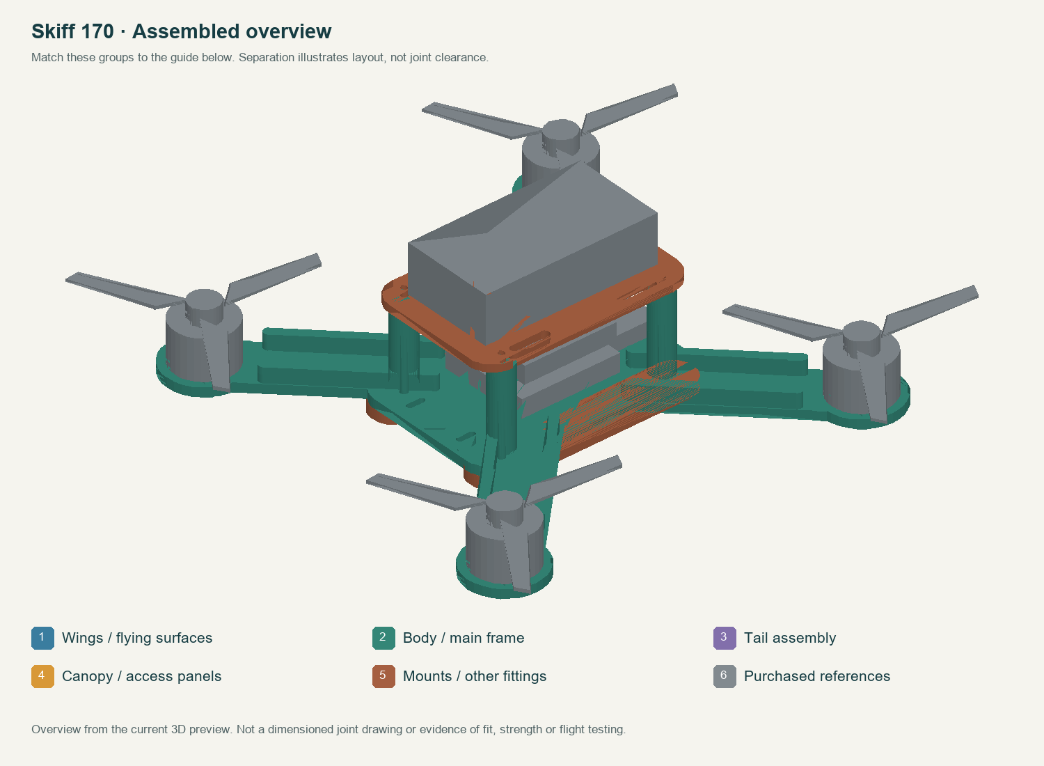
Before printing
Use the supplied orientation and 100% scale. The 3MF files contain geometry and arrangement, not a validated printer/material profile or ready-to-run G-code. Use the material listed for each plate. Slice with supports off where specified and inspect the first layers, bridges, thin-wall continuity and holes before printing.
Mounting and connection details
Coordinates refer to the assembled CAD datum, not the slicer’s rearranged plate. Dimensions below are millimetres unless stated otherwise.
| Interface | Dimension / part | Assembly action |
|---|---|---|
| Stack | Holybro 11082,31×30×6 mm; FlywooFW19003228,33×30.4×6.1 mm;20×20 M2 mount. | Retain soft grommets and insulation. Case envelopes fit; determine bolt/spacer length from the actual stack and cable bends. |
| Motor mounts | Four iFlight XING21404 3800 KV,1.5 mm shaft version; printed pad 3 mm thick. | M2×5 gives nominal 2 mm penetration. Check actual thread depth/winding clearance before tightening. |
| Props | Gemfan 3016,1.5 mm bore; twoCW and twoCCW. | Use correctly engaged purchased retaining screws for the actual 5.5 mm hub; no assumed screw depth. |
| FC firmware | KAKUTEH7MINI; boardv 1.5. | Include SRXL2 in the firmware build. UART2 SerialRX only, provider SPEKTRUMSRXL2. Verify board orientation and channels. |
| Receiver | SPM4650:5V →5V, ground →GND, signal →T2. | Use the regulated 5 V pad. Keep the antenna out of the battery/phase-wire bundle. |
| ESC harness | Flywoo pads G,V,1,2,3,4,C,T map to FC GND,B+,M1,M2,M3,M4,CURRENT,R7. | Use labelled pads and continuity checks. The two brands’ connector pin order is not assumed interchangeable. T/R7 telemetry is optional. |
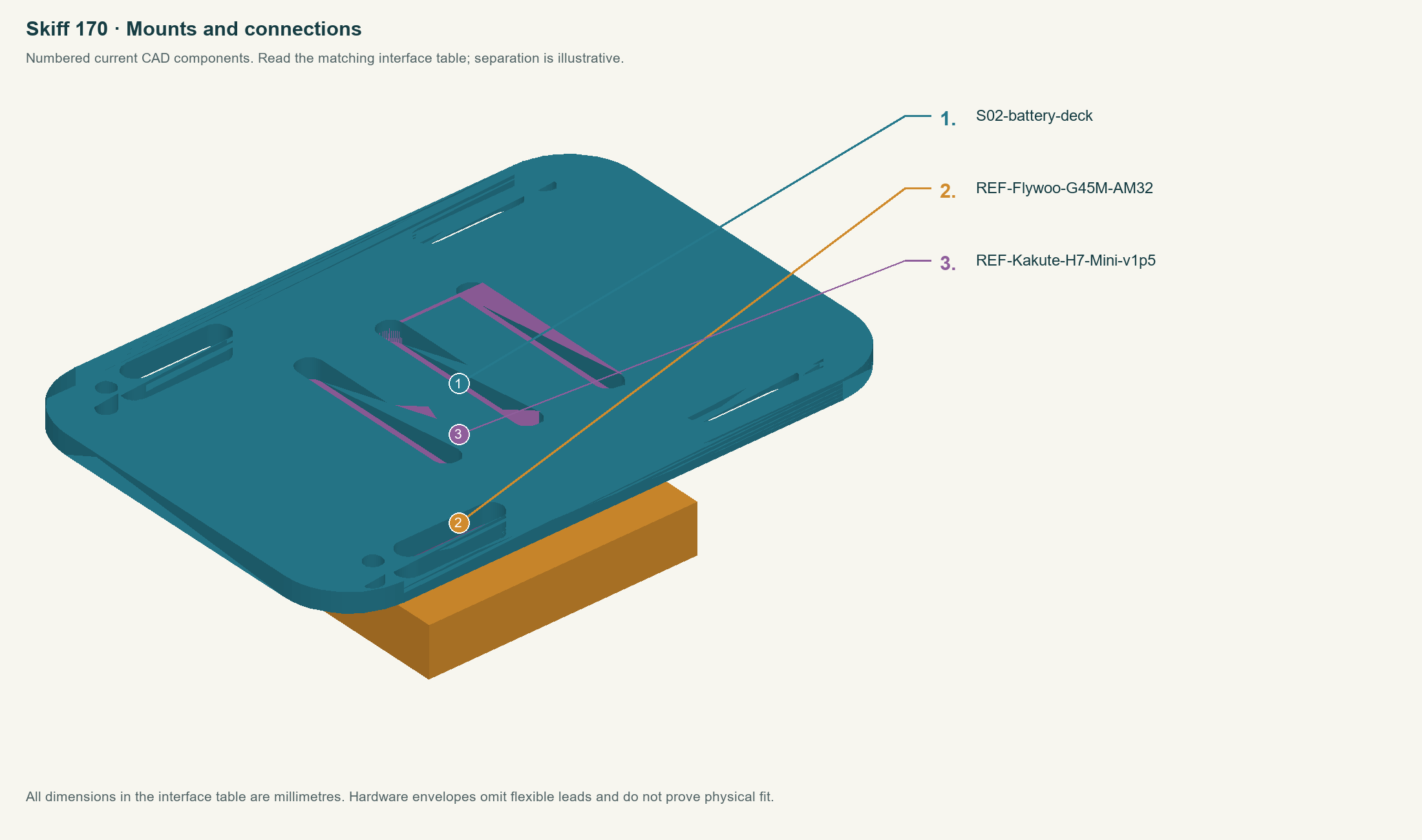
S02-battery-deckREF-Flywoo-G45M-AM32REF-Kakute-H7-Mini-v1p5
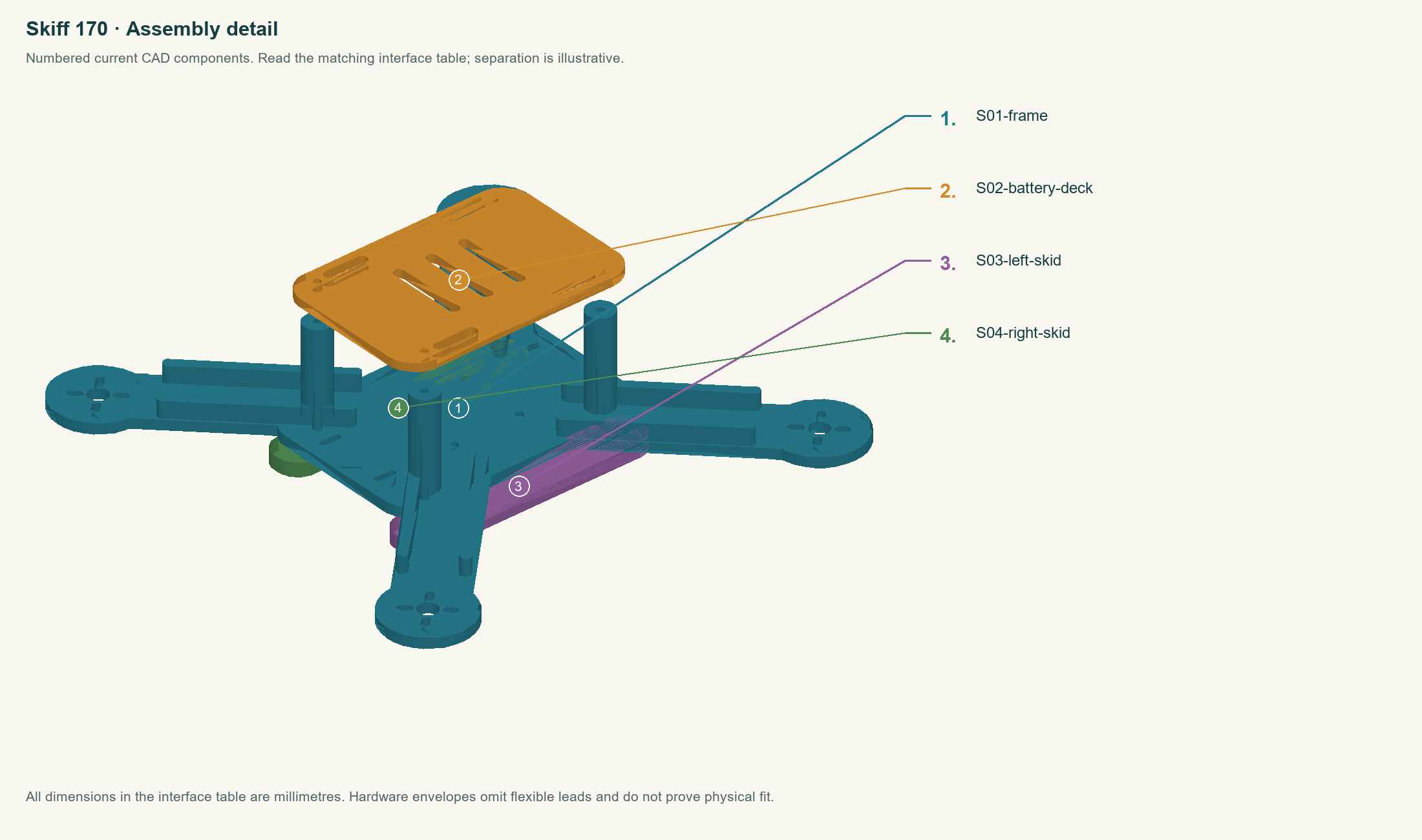
S01-frameS02-battery-deckS03-left-skidS04-right-skid
Build in this order
- Step 1
Print T01 motor interface and T02 through-bolt column in ASA; check the actual motor pattern, screw depth and column bores.
- Step 2
Print S01 frame/S02 deck flat on the ASA plate and S03/S04 skids on TPU plate; use supplied orientations, supports off and guide settings.
- Step 3
Orient arrow forward, place skids under frame and install motors with propellers removed.
- Step 4
Install the Kakute H7 Mini v1.5 and G45M AM32 ESC on the 20 mm pattern with soft isolation and USB access. Route the verified label-to-label harness and capacitor below the rotor planes. Leave room for the actual grommet/spacer/connector stack.
- Step 5
Thread battery straps through deck, then clamp skids/frame/columns/deck with four M2x40 through-bolts, washers and locknuts without crushing printed columns. Center and retain battery.
- Step 6
With all propellers off, select KAKUTEH7MINI firmware with SRXL2 support, UART2 SerialRX, SPEKTRUMSRXL2 and receiver signal on T2. Check board orientation, channel mapping, motor order/direction, arm switch and radio-loss response. Do not apply the old SpeedyBee current calibration.
- Step 7
Measure exact 3S/3016 motor current and thrust, prove frame and battery retention, check vibration/clearance and tune. Only after commissioning fit the matching CW/CCW props for a controlled hover evaluation.
- Use 3S with the selected G45M; the product title/URL says 2–6S but the board specification is 3–6S. Do not copy the old SpeedyBee current-sensor calibration.
- With props removed, confirm mixer motor number and actual direction one motor at a time. CAD creation order is not flight-controller motor order.
- No flight tune, GPS rescue or autonomous mode is supplied. Verify deliberate arming and receiver-loss disarm/motor stop before propeller fitting.
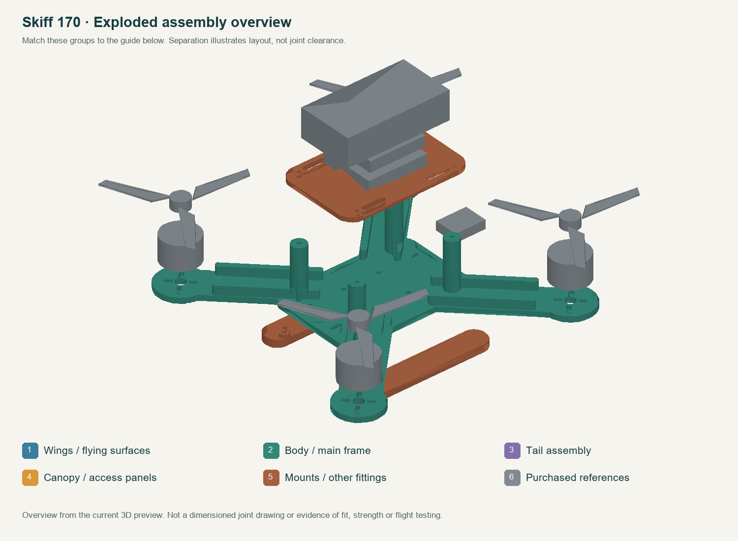
Power and radio setup
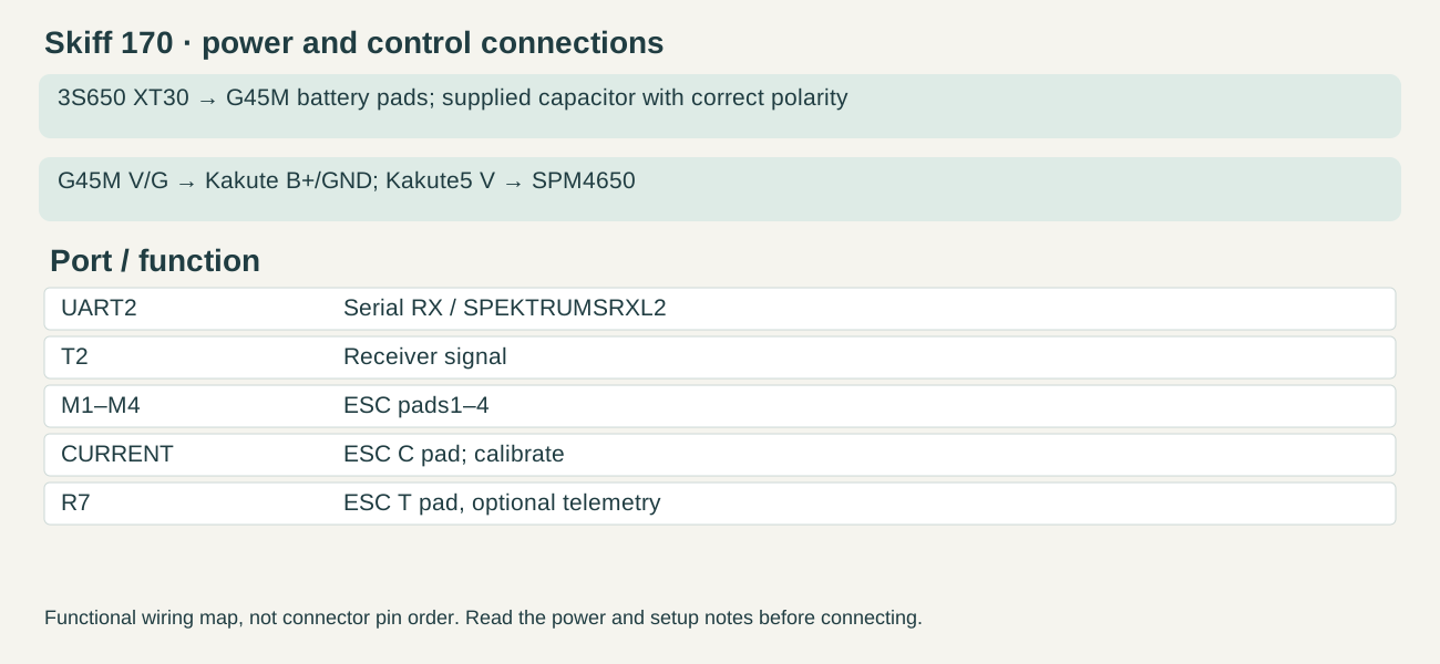
- G45M pad order visually checked on the manufacturer’s dimensioned board image; wire by label, never by an assumed plug order.
- Use current-limited first power and no propellers for configuration.
Keep propellers removed (and Rotor motors disconnected) during setup. Check polarity and regulated bus voltage before plugging in the receiver/servos. Center servos before fitting horns; check neutral, direction and free travel before connecting rods. Configure throttle cut and receiver-loss response, then test them on the installed system.
Fit and bond method
- Dry-fit and mark orientation, contact lands and insertion depth before mixing adhesive. Record actual tube, printed socket and coupon dimensions.
- Use an adhesive whose maker supports both actual materials. Prepare only the intended bond lands as directed; remove dust and let surfaces dry. Do not solvent-wipe a filament without checking compatibility.
- Make matching sacrificial coupons with the same filament, orientation, carbon/wood if applicable, preparation and adhesive. Cure for the maker’s complete schedule and test the joint before committing to inaccessible or structural bonds.
- Bond on an alignment jig. Keep hinges, captive nuts, moving shafts, servo cases, leads and access covers free. Retain evidence of cure, bondline fit and test behavior; no adhesive process or load rating is established by these files alone.
Fasteners and linkage lengths
A listed starting screw length is not permission to bottom a screw in a motor or crush a servo ear. Measure the mount, washer and nut stack; verify locking-thread engagement and moving-part clearance. For a blind threaded motor hole, compare protrusion below the mounting face with the manufacturer’s maximum permitted penetration.
Set servos to neutral and surfaces straight. Install the chosen retained ends with their required thread engagement, measure the ball/pin-center distance, then mark the rod between those actual ends. Viewer centerline lengths are not bare rod cut lengths. Check both travel limits and combined gear/door states before final locking.
What still prevents a completed flying release
- Physical stack/harness fit, exact propeller screw engagement, current/thrust and battery margin, frame/vibration/failsafe and flight tuning.
Use the measurement record to report actual fits and test results. A geometric pass is not a structural rating, slicer validation or flight test.
Detailed source guide
Included in ZIP: Retained model-specific source instructions. Current R2 interface and replacement instructions above take precedence where a retained source describes an earlier revision.