
3D Hangar · Current R2 package · 31 October 2026
Tern 1100 build guide
Interactive 3D viewerFree · name and email required
Print and fit prototype: physical printing, installed hardware and flight validation remain outstanding.
What changed
- Completed dimensioned motor/servo installation notes, wiring and linkage-setting diagrams.
- Clarified motor-to-cross versus cross-to-firewall patterns, prop centering and the battery’s maximum case allowance.
- Added a sealing, dry-mass, float and control-travel record; retained 19 printed pieces.
These are digital design and documentation checks. No new physical print, load, radio, water or flight tests have been performed.
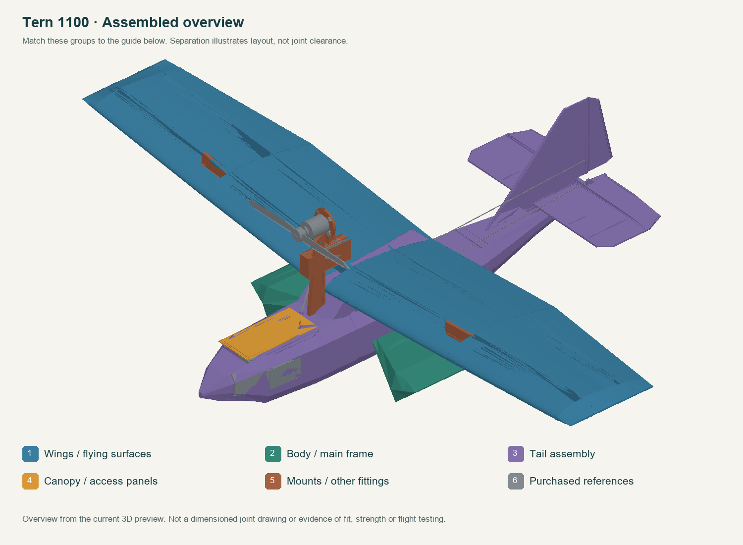
Before printing
Use the supplied orientation and 100% scale. The 3MF files contain geometry and arrangement, not a validated printer/material profile or ready-to-run G-code. Use the material listed for each plate. Slice with supports off where specified and inspect the first layers, bridges, thin-wall continuity and holes before printing.
Mounting and connection details
Coordinates refer to the assembled CAD datum, not the slicer’s rearranged plate. Dimensions below are millimetres unless stated otherwise.
| Interface | Dimension / part | Assembly action |
|---|---|---|
| Motor mounting | Skywalker 2312SL1250 KV supplied X-mount outer Ø34 mm pattern, rotated 45°. | Four M3 through-bolts with washers/locknuts. Motor-to-X-mount screws are separate; use the supplied hardware and verify engagement. |
| Prop adapter | APC9×4.5E LP09045E; supplied motor adapter M5×0.8. | Fit correct 5 mm APC centering ring. Check washer, hub and nut engagement before powered use. |
| HS-55 mounts | 28.6 mm ear pitch, holes X200.1/228.7 at Y±17; pad top Z48.7. | Four M2×8 through-bolts with washers/locknuts; confirm full locking engagement and actual horn sweep. |
| Pylon | M2 bolt through nominal 12.4 mm cheek stack. | Select a length that engages all locking threads after washers; M2×16 may be too short. Do not clamp only a thin shell. |
| Pushrods | Two 1.2 mm steel rods in 2 mm OD nylon guides; four retained end connections total. | Viewer path lengths 503/522 mm are not cut lengths. Fit both horn axes and complete travel before bonding inaccessible guides. |
| Battery | Tattu 1050mAh3S75C XT60; reserve 76 ×38 ×21 mm. | Only 0.4 mm per-side nominal tray margin. Trial actual pack, pads, straps and lead bends before closing the hull. |

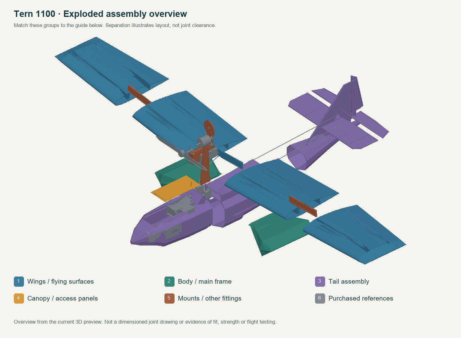
M-pylonM-firewallM-ESC-spray-hoodservo-left HS-55 with mounting earsservo-right HS-55 with mounting ears
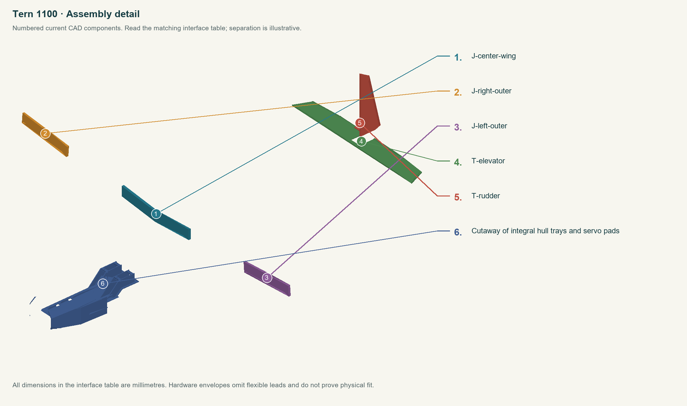
J-center-wingJ-right-outerJ-left-outerT-elevatorT-rudderCutaway of integral hull trays and servo pads
Build in this order
- Step 1
Print and fit all eight samples using production materials, including the servo cradle with 12.8 mm roof span and motor/ESC-hood patterns.
- Step 2
Use eight supplied full plates, 0.4 mm nozzle, 0.2 mm layers, brim and supports off; keep supplied orientations. Calibrate foaming shell material; keep joiners dense and motor pieces ASA.
- Step 3
Dry-fit 14 mm hull collar overlaps. Install HS-55 servos on internal ear pads, outward 10 mm arms, pushrod guides, battery straps and fixed receiver tray before bonding/sealing hull segments and sponsons.
- Step 4
Bond the pylon mortise and fit the firewall tongue. Select the M2 retention bolt from the actual 12.4 mm cheek stack plus washers and full locknut engagement;16 mm may be short. Fit the supplied 45° X-mount with four M3 through-bolts. Strap the 40A V2 ESC independently from the spray hood; keep heat flow and service access open.
- Step 5
Fit center V joiner for 5-degree dihedral and correctly oriented outer joiners with 60 mm engagement per side; align and bond on a jig before bonding wing to saddle.
- Step 6
Fit stabilizer around fin pads, tape-hinge elevator and rudder with the specified gaps, and install guided steel pushrods with positive clevis retention. Treat initial throws as provisional bench settings.
- Step 7
Connect NX8 channels 1 throttle/ESC BEC, 3 elevator and 4 rudder; verify throttle cut, failsafe, range and directions. Leave stabilization disabled until configured and checked.
- Step 8
Qualify sealant and canopy tape on samples, leak-test the empty hull, then record actual mass and 52-57 mm aft-LE CG, distributed structural load, fresh-pack power/temperature and ballasted flotation. Complete dry-flight and water-taxi evaluation before considering water takeoff.
- Seal the printed hull, sponsons and seams using a coating tested on the chosen filament. The canopy rim and spray hood are not waterproof seals.
- Leak-test an empty hull first, then a ballasted hull at measured operating mass and CG, without live electronics. Record waterline, freeboard, tilt recovery and leakage before any powered water trial.
Power and radio setup
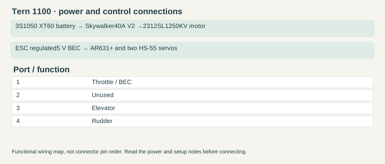
- Three-channel rudder/elevator aircraft; no water rudder. Keep brake/reverse disabled for initial bench setup.
- Fit the purchased propeller only after direction, throttle cut and failsafe checks.
Keep propellers removed (and Rotor motors disconnected) during setup. Check polarity and regulated bus voltage before plugging in the receiver/servos. Center servos before fitting horns; check neutral, direction and free travel before connecting rods. Configure throttle cut and receiver-loss response, then test them on the installed system.
Fit and bond method
- Dry-fit and mark orientation, contact lands and insertion depth before mixing adhesive. Record actual tube, printed socket and coupon dimensions.
- Use an adhesive whose maker supports both actual materials. Prepare only the intended bond lands as directed; remove dust and let surfaces dry. Do not solvent-wipe a filament without checking compatibility.
- Make matching sacrificial coupons with the same filament, orientation, carbon/wood if applicable, preparation and adhesive. Cure for the maker’s complete schedule and test the joint before committing to inaccessible or structural bonds.
- Bond on an alignment jig. Keep hinges, captive nuts, moving shafts, servo cases, leads and access covers free. Retain evidence of cure, bondline fit and test behavior; no adhesive process or load rating is established by these files alone.
Fasteners and linkage lengths
A listed starting screw length is not permission to bottom a screw in a motor or crush a servo ear. Measure the mount, washer and nut stack; verify locking-thread engagement and moving-part clearance. For a blind threaded motor hole, compare protrusion below the mounting face with the manufacturer’s maximum permitted penetration.
Set servos to neutral and surfaces straight. Install the chosen retained ends with their required thread engagement, measure the ball/pin-center distance, then mark the rod between those actual ends. Viewer centerline lengths are not bare rod cut lengths. Check both travel limits and combined gear/door states before final locking.
What still prevents a completed flying release
- Actual hardware/linkages, seal durability, buoyancy/water handling, current/cooling, measured mass/CG and flight tests.
Use the measurement record to report actual fits and test results. A geometric pass is not a structural rating, slicer validation or flight test.
Detailed source guide
Included in ZIP: Retained model-specific source instructions. Current R2 interface and replacement instructions above take precedence where a retained source describes an earlier revision.