
3D Hangar · R3 · 1 November 2026
Rotor 235 build guide
Interactive 3D viewerFree · name and email required
Exact Rotor purchase and measurement checklist
Unpowered measuring package. The operating mechanical design is not complete: shaft-stack, gear-mesh, swash and boom dimensions are still required.
What changed
- Added a complete six-piece shaft/bearing measurement fixture and a three-size bearing fit ladder.
- Selected the OEM motor plate and retained OEM antirotation/tail-motor interfaces, keeping the frame printed.
- Documented the missing dimensions that must be measured before the rotating mechanism can be completed.
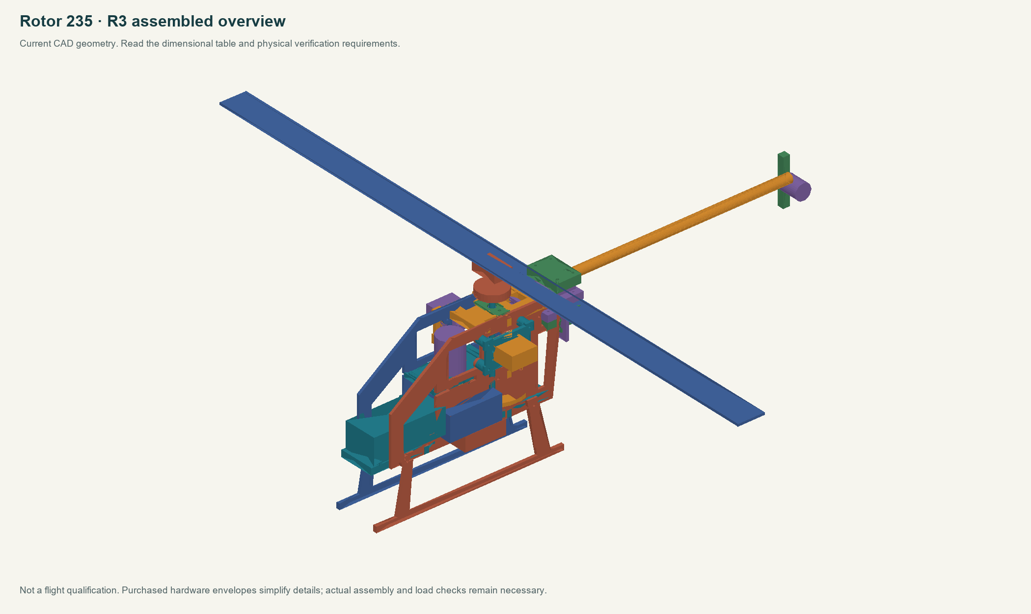
Before printing
Use 100% scale and the supplied orientation. These 3MFs are geometry-only, not printer profiles or G-code. Check the sliced first layers, bridges, thin walls and holes. Hardware cases and a digital clearance pass do not establish strength, fatigue, heat, radio reliability or flight performance.
What can be printed now
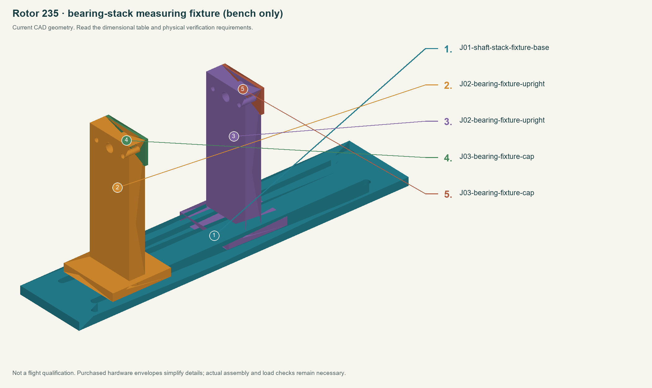
- Print J04 first. One, two and three notches identify 8.00, 8.05 and 8.10 mm bearing seats. Test an actual BLH4515 bearing by hand; reject a loose seat or a distorted/binding race.
- Print J01 once, J02 twice and J03 twice. Fit the real bearings in the upright pockets and retain the outer races with caps. Use four M2×12 fasteners; the shaft must rotate by hand without being clamped by a cap.
- Clamp both upright feet to the slotted base with M3 fasteners. Align them using the actual shaft. Their displayed 60 mm separation is merely a fixture example, not an aircraft datum. Stabilize/elevate the base to clear projecting nuts.
- Fit the actual collar, main gear, hub and head block by hand. Record the axial stack, end float and bearing-center distance from the real components. Keep all motors disconnected.
- Measure the OEM motor plate, pinion and gear mesh next; then swash guide/horns/links through full travel; then boom and tail mount. These measurements determine the next production-frame geometry.
Selected mechanical interface route
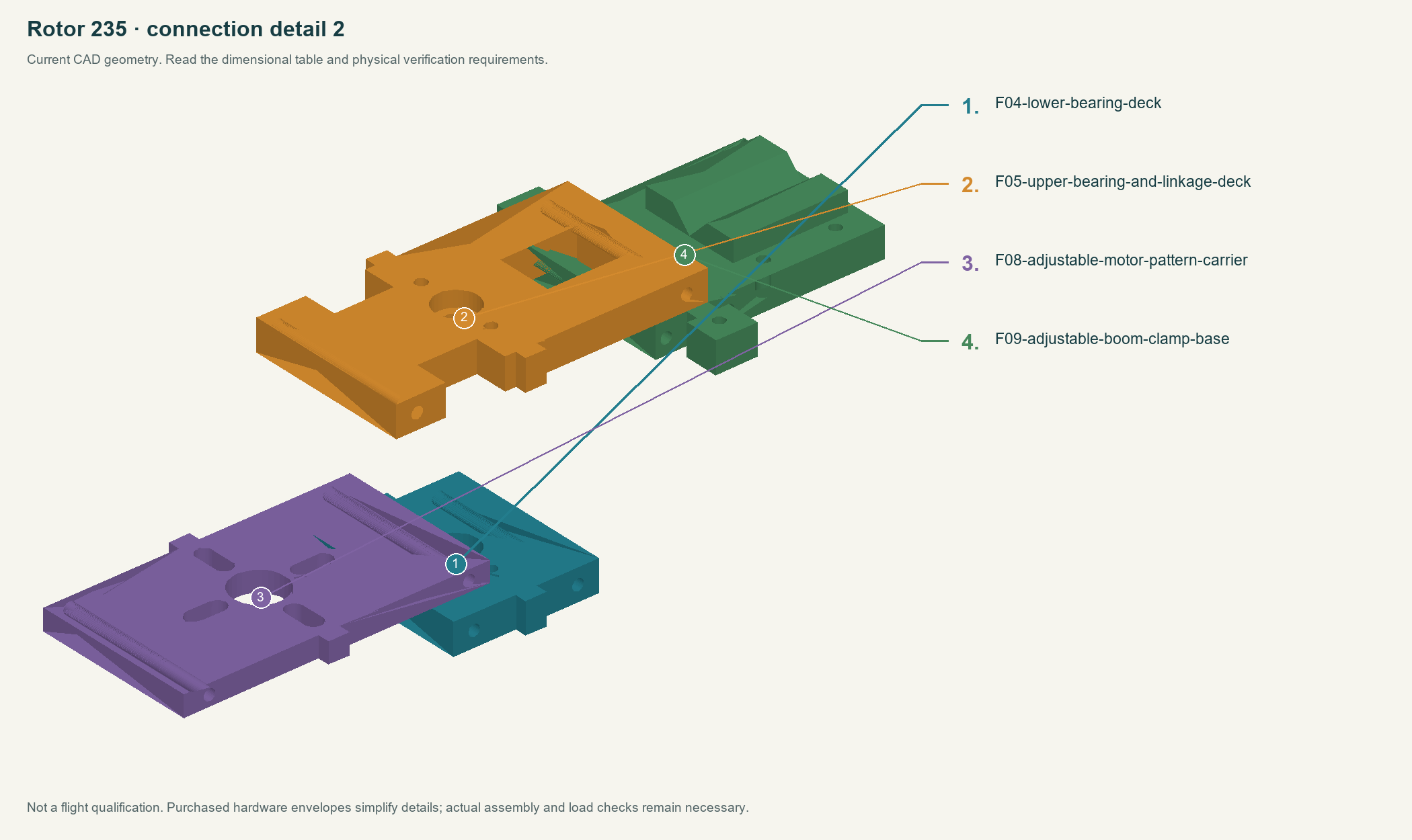
The main frame remains printed. Use the small purchased BLH-1781 motor plate, BLH-1783 antirotation bracket and BLH-1777 tail motor mount with the matching Revolution 235 mechanism. A whole helicopter is not required. Published listings identify supplied fasteners but do not establish the frame attachment datums.
| Measure from actual hardware | Why it is required |
|---|---|
| BLH1506 shaft/collar + BLH4515 bearings + main gear | Shaft length, shoulders/cross-holes, collar position, bearing-center spacing, gear hub and bolt stack. |
| SPMX-1083 + BLH-1781 + BLH-1785 | Mount hole pattern, boss/shaft, permissible screw engagement, pinion location and actual mesh center. |
| Swash + BLH-1783 + KST horns/links | Guide attachment and travel, ball centers, neutral link lengths, full cyclic/collective clearance. |
| Boom + BLH-1777 tail mount | Actual section, OD, length, indexing and retained tail attachment. |
The existing motor slots and boom clamp are fitting studies, not verified operating mounts. Do not run the mechanism or advertise this as a completed helicopter kit. The missing dimensions cannot be obtained from package dimensions or scaled product photographs.
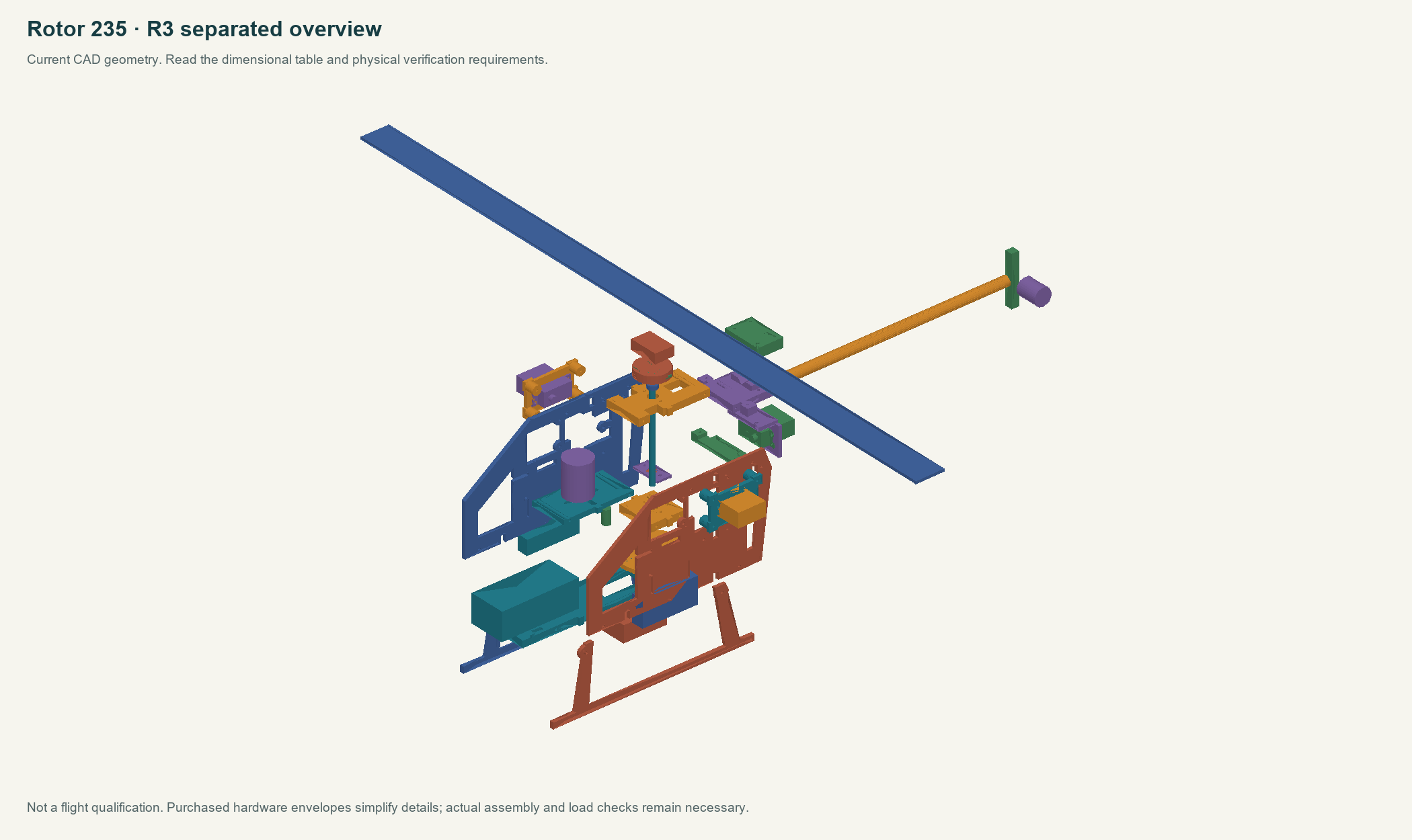
Verification still required
- Actual shaft/collar/bearing/gear stack, motor-plate hole datums and mesh center, swash-guide and horn/link dimensions, boom section and indexing.
- The preview’s 42 mm bearing spacing, 106 mm shaft and 52 mm gear are still schematic. Do not use them as production dimensions or run the rotor.
No new physical print, load, electrical or flight tests have been performed. The current guides record what was checked digitally and what still needs measured evidence.